This thread has been locked.

If you have a related question, please click the "Ask a related question" button in the top right corner. The newly created question will be automatically linked to this question.

TPS25751: TPS25751 BQ25798 dead battery function

Part Number: TPS25751
Other Parts Discussed in Thread: BQ25798, , BQ25792

Tool/software:

Hi, 

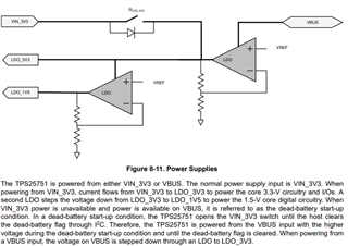
I have TPS25751S combined with BQ25798, 2s, safe mode, both ADCINx = 0, sleep mode on. There is also a controller, but it does not touch the system at the moment. Everything works so far, if battery voltage is above 5V (e.g. USB voltage 12V and current of 2A --> battery charge current or 3A). If I use a PD-mains charger and the battery is below 5V sometimes it starts charging, especially after power down and on. But  sometimes not. In some cases permanent 5V  is visible at the USB-C input with no charge current, sometines 5V pulses with some ms duration after some 200ms pause is visible. The VIN_3V3 is about 2.7V, also the LDO_3V3 (it should be powered from VBUS in that case and be at 3.3V?). The LDO_1V5 is o.k. There is 5V at the VBUS, but not at the PPEXT after the transistor switch (BQ VBUS). Sometimes I saw also correct voltage at the LDO_3V3 and the charging does  work either. 

In the data sheet BQ I saw a lower batttery limit of 5V. Does it mean dead battery charging does not work below 5V?

Best reagrds

Karl

  • Hi Karl, 

    Can you provide a block diagram or schematic of your design along with the TPS25751 JSON configuration? 

    Thanks and Regards,

    Raymond Lin

  • USB_PDX_2_2.pdf

    Hi Raymond,

    here the schematic of the PD part. The liquid detection circuit is disconnected at the moment. 

    One furhter question which came up today: I found that the INT output of the BQ25798 is low when the part is in idle mode (no charging or discharging) and high when charged, i.e. in idle it pulls about 300uA through the 10k resistor (which his too much). How can this be avoided or is it possible to disconnect this connection to the TPS25751?

    Best regards

    Karl

  • Hi Karl, 

    Reviewing the schematic you provided, will provide feedback on the TPS25751 portion. Do you have the JSON for TPS25751 or is that not created yet? 

    One furhter question which came up today: I found that the INT output of the BQ25798 is low when the part is in idle mode (no charging or discharging) and high when charged, i.e. in idle it pulls about 300uA through the 10k resistor (which his too much). How can this be avoided or is it possible to disconnect this connection to the TPS25751?

    You do not need to connect BQ25798 INT to TPS25751. 

    Thanks and Regards,

    Raymond Lin

  • PDX_0_8_1.rar

    Hi Raimond, 

    here the JSON file. 

    Best regards

    Karl

  • Hi Karl, 

    The VIN_3V3 is about 2.7V, also the LDO_3V3 (it should be powered from VBUS in that case and be at 3.3V?).

    During this scenario, is the system powered on through the battery or through the Type-C connection with a source? If TPS25751 VIN_3V3 is not at a stable 3.3V (2.7V as you described), it may put the PD in an abnormal state of not being able to boot-up. It looks like the VIN_3V3 source is from UBAT0 connected to BAT of BQ25792, is that correct? 

    In the data sheet BQ I saw a lower batttery limit of 5V. Does it mean dead battery charging does not work below 5V?

    I'll loop in the BQ team for further support on this query. From TPS25751 perspective, the PD can powered on either through VIN_3V3 (3.3V) or its VBUS pin. If TPS25751 is first booted from VBUS, the PD internal power topology will use VBUS as the primary power source until the dead battery flag is cleared. See screenshot from TPS25751 datasheet below: 

    Thanks and Regards,
    Raymond Lin

  • Hi Karl,

    With VBUS>VBUSUVLO ~=3.4V, the charger enters 100mA trickle charge if the voltage at BATP <=2.5V.  Then starts precharge current until the battery is above VBATLOWV, when it switches to fast charge.  

    Regards,

    Jeff

  • Thanks Raimond, Jeff, 

    Your question above; the VIN_3V3 is comming from the uC supply which is normaly 3.3V, but in sleep mode it may drop down to 2V depending on the battery status (uC  (MSP430F) works with this voltage). I will try to generate a stable 3.3V for TPS25751 from VBUS and came back later if I have further results. 

    Regarding the second answer above: do I need to clear the dead battery flag or ist done automatically? When is a boot necessary, i.e. when is the TPS25751 memory lost?

    Regarding Jeffs answer: I did not see any current, also not the 100mA.

    I will came back after I did further tests. 

    Best regards

    Karl 

  • Hi Raimond, 

    in the meantime I modified the power supply. I had to switch off VIN_3V3 and the 5V because the power comsumption is too high (in the mA range). 

    Everything is o.k. when I connect a mains charger to  charge the battery. It starts up in dead battery mode (supply from VBUS) and charges my battery. 

    But the problem is now that when I connect the (to be charged) smartphone the TPS25751. It goes to dead battery mode (as there is no internal power) and sink mode and cannot charge the smartphone (it discharges the smartphone). I tried to reset (successfully, 00000000 in the register) the dead battery bit but it doesn't work, it does not change the TPS to source mode. 

    The procedure is the following: the part is in sleep mode and and VIN_3V3 and 5V  is witched off. Then I connect the smartphone which makes the TPS going to sink mode (and dead battery mode, probably also a reboot from EPROM). Then I switch on the power supply of the TPS (VIN_3V3 and 5V after some seconds) and send a DBfg command. --> Nothing happens.  

    1. question: do I need to have a total reset and new reboot?  

    2. Can I prevent the TPS25751 from starting a sink or source mode during my sleep mode? i.e. avoiding the dead battery mode? 

    Best regards

    Karl

  • Hi Karl, 

    Just to clarify, the DB flag will always raise if TPS25751 is first booted from VBUS and not VIN_3V3. It is then up to the MCU/system level implementation to decide when the DB flag should be cleared (i.e. VIN_3V3 is stable, battery level hits a certain level, etc.)

    The procedure is the following: the part is in sleep mode and and VIN_3V3 and 5V  is witched off. Then I connect the smartphone which makes the TPS going to sink mode (and dead battery mode, probably also a reboot from EPROM). Then I switch on the power supply of the TPS (VIN_3V3 and 5V after some seconds) and send a DBfg command. --> Nothing happens.  

    The DBfg command only clears the dead battery flag, it does not initiate a power role swap with the connected port partner. After you send DBfg, you'll need to instruct TPS25751 to send a PR_Swap request with the connected port partner using 4CC command "SWSr" (Swap to Source):

    2. Can I prevent the TPS25751 from starting a sink or source mode during my sleep mode? i.e. avoiding the dead battery mode? 

    In Port Control (0x29), there are two register fields if you desire the TPS25751 to automatically swap to source/sink. See screenshot below for bitfield7 and 5: 

    Let me know if you have any further questions or concerns! 

    Thanks and Regards,

    Raymond Lin

  • Hi Raimond, 

    Thanks. 

    To your first answer: It is clear that the boot with VBUS only will raise the dead bat flag. But I don't know whether a source or sink is connected when booting from VBUS. In my example (dual power role)  the Port always switches to sink mode (of TPS25751) when booted from VBUS*. If an external source (e.g. mains charger request a sink) is connected and I swap  to source as proposed  will there be conflict or what happens then or will it stay at sink mode? Or happen this: "but failed to complete per the PD spec."? How can the "time out" then be recognized? And the correct command? Do I have to check certain bits? And after this command 'SWSr' is the TPS still in the dual power role or switched to source only mode?

    Unfortunately I cannot see which external part is connected (sink or source) because the smartphone (should be sink) acts as a source. If the TPS goes to sink with the smartphone (ext source) and I reconnect physically the USB connector it will automatically switch to source (ext. sink). So the best for me seems to be to reconnect the USB interface somehow. But is this possible electronically e.g. by a certain command? I tried also "DBfg" followed by  "Gaid" command, but it don't work either. 

    Above  answers I think are also valid for your second proposal. 

    Best regards

    Karl

    *) If I connect the USB when VIN3V3 and 5V is active, the TPS swiches to the correct behavior (sink with ext. source, source with ext sink). 

  • Hi Karl, 

    Let me check on this and get back to  you early next week. 

    Thanks and Regards,

    Raymond Lin