This thread has been locked.

If you have a related question, please click the "Ask a related question" button in the top right corner. The newly created question will be automatically linked to this question.

TPS23882B: PD not classifying as expected

Part Number: TPS23882B
Other Parts Discussed in Thread: CSD19538Q2,

Tool/software:

Hello,

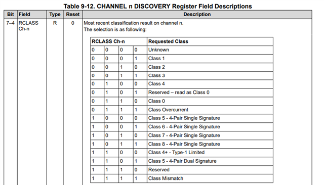
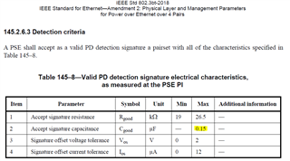
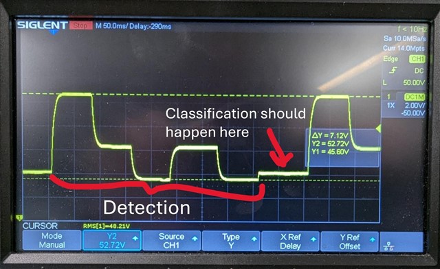
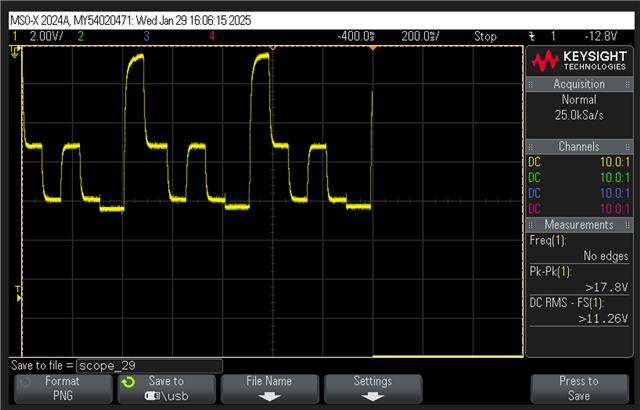
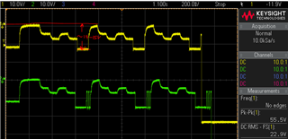
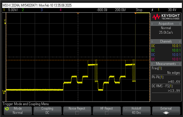
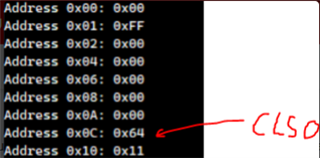
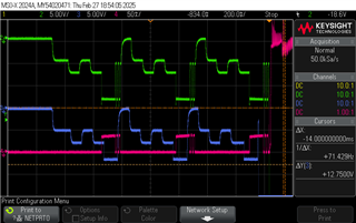
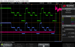
We're running into an issue with our TPS23882B PSE regarding classification in semi-auto mode. Our PD is supposed to classify at class 4, but when we plug it into our board, it's consistently classifying at class 0. Detection is working as expected.

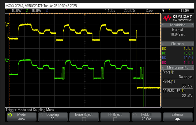
We have the eval kit for the TPS23882B, and when we plug the PD into that, it's classifying properly at class 4, even when using the same register settings. This leads us to believe that there may be an issue with our PSE configuration.

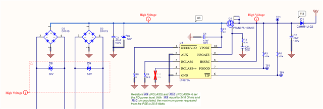
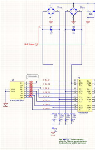
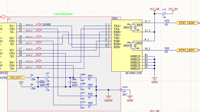
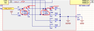
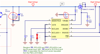
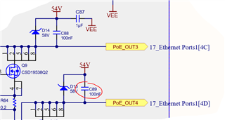
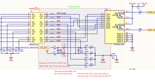
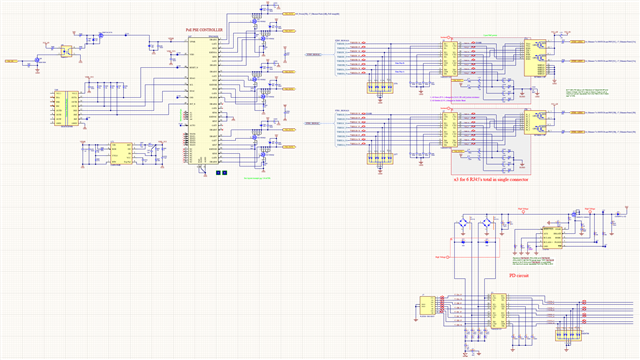
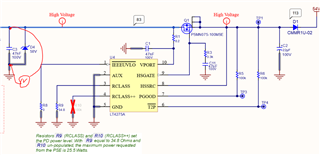
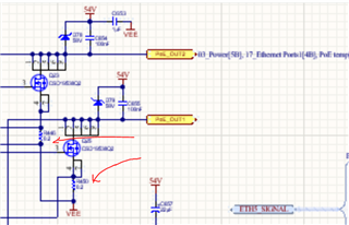
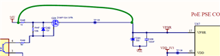
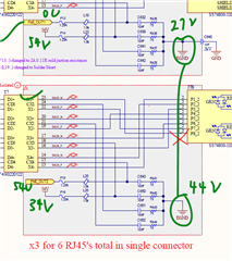
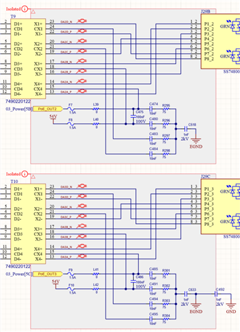
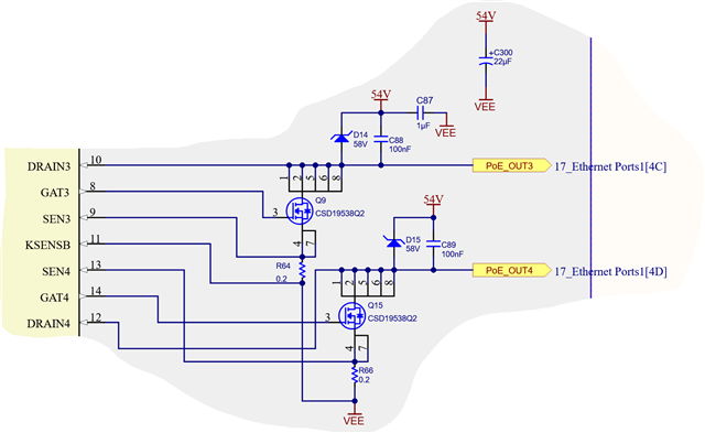
I've attached an excerpt from our schematic that shows how each pair of PoE ports are wired up to the PSE:

Any idea what may be going on that's causing the PD to not classify properly? Please let me know if more information is needed.

  • Hi Noah,

    Thanks for reaching out!

    The PSE schematic looks good to me.

    - Can you also share the PD's schematic?

    - How many channels do you have in the design? Have you tried all channels? 

    - Class-0 could be the classification current is too low. And could you check the "DISCOVERY Register" of 0Ch - 0Fh and "ASSIGNED CLASS CHANNEL" Register of 4Ch - 4Fh? 

    Best regards,

    Diang 

  • Hi Diang,

    I don't believe the PD is the problem, given that the PSE eval kit classifies the PD properly, but I'll attach an excerpt from the schematic just in case:

    We are using 6 channels on the PSE in our design, and we are seeing the same issue across all ports. The number reported by the discovery register is 6(0110b) for the port in question.

  • Hi Diang
    Kist some more schematic details
    PD RJ45:

    PSE RJ45: 

  • Hi Tom and Noah,

    Thanks for the schematic. Still looking for the register dump.

    It may be worth to try to remove C464 and C472 capacitance considering there are too much caps between +DC and -DC or a channel. This may cause detection issue

    Best regards,

    Diang

  • Hi Diang,

    Here's a dump of the relevant PSE registers taken after channel 1 has finished detection/classification but before power up:

    If we ignore the fact that the classification result was not 4 and power on that port anyways, we get the following register dump after power up has completed:

    I tried to pull all the relevant registers for channel 1, but please let me know if there are others that I missed. Also note that we're servicing and clearing the event and interrupt registers in our code, hence why those registers are all 0. There were no fault events generated by the PSE during the detect/classify/power on sequence.

  • Hi Diang,

    We removed those two capacitors from our board, but unfortunately we're still getting the same issue.

    This is the PSE output detect/classify signature we're seeing on our end, as measured with an isolated scope:

    As you can see from the capture, the detection cycle completes successfully with no issues. However, where the classification stage should start by the voltage being pulled low, instead the voltage stays high.

  • Hi Noah,

    Thanks for updates. 

    I am currently working on verification. Will be back for E2E support from Jan 20th. Thanks for your patience. 

    Best regards,

    Diang

  • Hi Diang,

    Just wanted to follow up on this to see if you had any updates for us.

    Thanks,

    Noah

  • Hi Noah,

    The PoE team will be traveling until Feb 4th. Sorry for the delay on the response and thanks for your patience.

    Best regards,

    Diang

  • Hi Diang
    Some further updates from our testing:

    We have tested multiple boards and what we see is some ports classify correctly and some do not.

    The ports that classify correctly are not consistent between boards - some boards have 2 some 5, so correct classification is not always following channel pairs.

    Yellow: Port classifying as 0 usually, Green: port classifying as 4 (correct) Measured after POE_OUTx fuse  

    Each failed Port is different on the voltage before turn on, many look like below which does suggest we are not seeing even close to the 40mA at the PSE 0.2R sense resistor:


    We made below mods to each of our 6 PoE outputs. See red notes. 

    Above mods help. We will see, on average, one or two more ports classify correctly, but in some cases we see no difference on a ports waveform.


    We have tested our PDs (ADI LT4275A) on the TI Boost-PSETHR8 dev board, and they classify correctly so we know issue must be our hardware/firmware.


    Hardware differences between dev board and ours:
    1. Do not have a 1nF 1000V cap between 75R filters and plane under Transformer/RJ45. I did mod two channels (1 pair) up with this mod but saw no difference.

    1a. We are typing RJ45 shield to digital ground for ease of mechanical. I did modify one unit with mode 1 above so RJ45 shield was tied to EGND and saw no change.   

    2. FETS are CSD19538Q2 not Q3. Slightly lower power rating (13.1 vs 14A)
    3. 2x 22uF 100V bulk caps on 54V, not 2x47uF 100V

    4. Layout: Do to space constraints the above PoE parts are closer to the RJ45 than the PSE.

    thanks tom     

  • Hi Tom, 

    Thank you for the updates. The PoE team will get back to you soon. 

    Best Regards, 

    Aya Khedr

  • Hi Aya,

    I just wanted to ping this on behalf of Noah to see if the team had any additional updates? Thank you. 

  • Hi Abigail,

    I just back from TBK. Will try to get back to you in this week. Thanks for your patience. 

    Best regards,

    Diang

  • Hi Noah and Tom,

    Thanks for your patience. From register map, we did see the 0Ch shows "Request Class-0". What could happen is the classification current is too low. What I see is the port out put voltage during classification is low as ~14 - 15V. This is lower than the 15.5V to 20.5V as expected. 

    On the PSE side,

    What may happen is the VPWR pin is not directly connected to the "54V" , this may cause the PSE cannot accurately output port voltage of 15.5 - 20.5V as VPWR - DRAIN. Could you mind to share a full PSE schematic? 

    Or if there is any resistance in series with the highlighted loop that cause insufficient classification voltage.  


    Another cause may be layout related that cause voltage Kelvin sensing is coupled with current (less possible since Iclass is so low). 

    On the PD side,

    DF01S as rectifier has a relatively high voltage drop (~0.75V @ 40mA 25C, 0.75V x 2 is the drop) , which may cause the voltage at PD side even lower than turning the classification regulator. A Schottky diode based rectifier will help to alleviate. 

    Best regards,

    Diang

  • Hi Diang


    Below is the complete PSE circuit & PD circuits 

    Your comment about resistance on PoE path is understood. We have modified the Fuse and removed a Ferrite from each PoE output to bring the resistance down. As you can see from schematic there is not much else in the current path. We have tried with short/long Cat5e/6A cables. PoE and PD controller circuits are within ~1.5" of RJ45's... 

    What is head scratching is we have many PoE ports that consistently classify correctly, without changing above components to reduce resistance. Most often the ports that do not classify correctly are seeing the lower end of ~8.5-14V, so not even close to 15.5V.   

    We do have the PD setup for 4 pair PoE power for future upgrades...not sure if this is an issue? 

    I have gone over the layout and nothing is jumping out at me to do with the Sense resistors.
      

    Thanks tom

  • Hi Tom,

    Thanks for sharing the full schematic. It may be related to the 1st guess: I saw the VPWR is not directly connected "54V", and port output directly connected to "54V". So the PSE voltage control based on VPWR - DRAIN will have an error with 54V - DRAIN to present 15.5 -20.5V. Could you try to directly connect "54V" to VPWR? 

    What may happen is the VPWR pin is not directly connected to the "54V" , this may cause the PSE cannot accurately output port voltage of 15.5 - 20.5V as VPWR - DRAIN. Could you mind to share a full PSE schematic? 

    Best regards,

    Diang

  • Hi Diang

    I shorted out the resistor and FET so that 54V (same voltage on PSE output) is directly connected to VPWR (pin 17). No change to Detect voltage or classification on the ports that do not see Class 4.

    What else do you want to see as far as the PSE schematic? We are powering the Device from a AC/DC brick that outputs 54V DC and all we do is filter before sending to PSE and PoE ports. 

    thanks tom  

  • Hi Tom,

    Thanks for your test.

    Could you help to remeasure the voltage between PD's C3 cap during PSE-PD is handshaking (detection + classification)? Just want to see how many voltage is during detection range. Detection uses current source control which may not  be influenced by diode forward or impendence in the loop. But classification is voltage source control which may be influenced. 

    And from the register the measure required Class is still Class-0?

    Besides, what is the package for your current sensing resistor (though classification current is very small)? Normally need 0805, > 0.3W power rating. Could you share a higher resolution pdf. schematic? 

    Best regards,

    Diang

  • PoE temp.pdf

    Hi Diang


    I have measured the resistance from the output FET(drain) to Diode bridge on the PDs. Seeing 0.7-0.8R on all 6 ports (3 of which classify correctly and 3 which do not).

    On the Ports that do not classify correctly we see Class 0 ~80% of the time, but occasionally see class 1, 2 or 3. Our desired class is Class 4, 25.5W.

    The classification does seem to follow the PSE port, not the PD's. I can swap around PD's and the classification on the ports do not change (other than the class 0 is sometime 1-3).  

    Sense Resistor is: Resistor, Thin Film, 0.2 Ohm, 1%, 1/3W, 0805.

    Capacitance of the Scope affects the classification (using isolation TX on Scope). Measuring at Tranzorb right at PD.
    When I scope ports that previously classify as 4 they now classify as 3 (voltage is ~11.7V). If I let things discharge for a few minutes , often first classification is 4 but all subsequent are class 3. 


    Class 4, Voltage is ~11.9V, If reboot will classify as Class 3 below:

    Class 0, Voltage is ~8.1V port that never classifies as 4 

    Did some Mods at the PD:

    Short out R1 8.2R resistor at PD VPORT pin - No change
    Remove C1 47nF capacitor at PD VPORT - No Change
    Remove D2 bridge as we are only 2 wire - Unit does not boot consistently but eventually recovers to previous class...interesting...

    thanks tom


  • Hi Tom,

    Thanks for your updates.

    From LT4275 datasheet, it may need a >12.5V voltage between VPORT and GND, otherwise LT4275 may not turn on its classification regulator and result in low classification current. TPS23882B should make a 15.5V to 20.5V at its ports (VPWR - DRAINx)

    We may need to check why the voltage is low at LT4275 eventually. Using the ~8.1V port:

    Step #1: check if VPWR - 54V - DRAINx, make sure they are the same when port is off. If not same, PSE side may have some issue for port voltage control.

    Step #2: During classification, check the 54V - DRAINx voltage, compare with PD's VPROT - GND voltage. Normally 54V - DRAINx will be 0.8 - 1.5V higher than the VPROT - GND voltage due to 2 x DF01S diode forwarding voltage. If the difference is higher than 1.5V, there may be some issue between the PSE and PD that takes extra voltage.

    Step #3: if no strange above, you may use a different PoE PD board and check if that board can pass class-4.  

    Best regards,

    Diang 

  • Hi Diang

    #1 Verified VPRW - 54V are the same voltage when port is off.

    #2 The Voltage at the PD while lower than the PSE by ~1.3-1.75V does seem consistent. Keep in mind I can move PDs around and they do not affect the classification. The particular PSE Port determines if the PD will classify correctly. And different boards have different ports that classify correctly. 

    It is looking more and more like we are just not detecting the 40mA correctly at the SENSE (detect lower current), on certain ports only regardless of what is hooked up (in some cases the 2 ports on a single SENSE will detect differently, one correctly the other not even close).

    Not able to scope the sense resistor without affecting reading.

    The layout is quite tight and I only have one via connection on each KSENSx to a dedicated ground layer (have 4 dedicated ground layers that connect this via to PSE Ground pad). I would not expect this single GND connection to affect the low current sensing though (as you mentioned)? We do seem to be detecting and tripping at 29W (ILim) reliably.


    Could there be a firmware aspect to this that we are missing? 
    Do you have gerber's for the TPS23882B1EVM-008? hard to tell from pdf's.

    thanks tom

  • Hi Tom,

    PoE team is doing internal validation tests and the reply on E2E may be delayed for 3 - 5 business days. Sorry for the delay and thanks for your patience.

    Best regards,

    Diang

  • Hi Tom,

    Thanks for your follow-ups. We saw when failure happens there is only one classification finger and the 0Ch register shows CLS 0. This should be caused by classification current less than 4mA.

    From PSE and PD sides: 

    1. PD side classification regulator is off, which is due to voltage on the PD side is lower than 12.5V. And we saw it is only ~8.1V at port. So I would guess this is the cause. 

    2. PSE side SENSE measurement is shorted. You can verify by measuring the resistance between KSENS and SENS. If the resistance is less than 0.2 Ohm, may even need to be less than 0.02 Ohm to cause a 40mA measured as <4mA

    Best regards,

    Diang

  • Hi Diang,

    I'm helping Tom and Noah investigate this issue. I tested the current drawn (using a non-invasive clamp-style current probe on the CAT5e cable) by the PD on 2 ports: one which classifies correctly, and one which doesn't. These ports are connected to the same PSE. The pink waveform shows current during the classification stage.

    When classification succeeds, I see the expected 40 mA draw from the PD (below - pink current measured on the green waveform's port).

    When classification fails, I see 0 mA draw from the PD (below - pink current measured on blue waveform's port). I agree that this is very likely due to the voltage seen by the PD being less than 12.5V.

    Do you have any ideas as to why the PSE is supplying less than 12.5V?

  • Hi Daniel,

    Thanks for your helping.

    We pervious discussed some possibilities that will cause port output less than 12.5V. I guess below two issues could be checked:

    1. From PSE side, it should output VPWR - DRAIN as 15.5 -20.5V. Shorting 54V and VPWR to make sure PSE have a correct sensing voltage. 

    2. I just noticed the two Bob Smith termination grounds are shorted, it may be a cause since when upper port is on, the Bob Smith termination ground is (54 + 0)/2 = 27V, but when below Bob Smith termination ground is doing classification as 20V, the Bob Smith termination ground is (54 + 34)/2 = 44V. This may also cause port voltage output issue. You may try to disconnect these two grounds and retry.

    Best regards,

    Diang

  • Hi Diang

    1) We shorted 54V directly to VPWR at pin 17 previously  - no change.
    2) We had already changed the Bob Smith terminations to add a 1nF 2kV cap in series with the Reference plane under RJ45's/ethernet transformers for each Giga Ethernet channel - no change.


    Thanks tom

  • Hi Diang
    Are there gerbers for the TPS23882B1EVM-008 and base eval boards? Very hard to tell from pdf's.

  • Hi Tom,

    PoE team is doing internal tests and the reply on E2E may be delayed for 3 - 5 business days. Sorry for the delay and thanks for your patience.

    Best regards,

    Diang

  • Hi Tom,

    I will send the PCB file to you in email. Thanks

    best regards,

    Diang

  • Hi Diang,

    I have found the root cause of our problem. Since we have a FET gating VPWR to come up after 54V, the PSE sees a spike of 26V on all drain pins, as it is being back-powered through the 54V/drain capacitors and into the DRAIN pins of the PSE.

    I confirmed this by connecting VPWR directly to 54V and replacing the PSE with a brand-new component. After doing this, all 6 ports classified correctly. I then reverted the change so that VPWR comes up after 54V through the MOSFET, and all 6 ports failed to classify correctly.

    Thank you for the assistance on this.

  • Hi Daniel,

    Thanks for your information and glad to hear the root cause is found!

    I will close this thread for now. Please reply or open a new thread if you have further questions.

    Best regards,

    Diang