This thread has been locked.

If you have a related question, please click the "Ask a related question" button in the top right corner. The newly created question will be automatically linked to this question.

LMG2100R044: Difference between results and calculations of efficiency data

Part Number: LMG2100R044
Other Parts Discussed in Thread: LMG2100EVM-078, , LMG2100EVM-097, LMG2100R026

Tool/software:

Hi all,

I would like to know the efficiency data of LMG2100R044 and LMG2100EVM-078.

My customer is evaluating the efficiency of Fsw=300 kHz with LMG2100EVM-078.

By replacing the current Si FET with LMG2100, the efficiency is expected to decrease by about 70%. However in fact, the efficiency is only reduced by about 20%.

I received the following data by email.

When (Fsw=300 kHz, Vin=47.85V, Iin=2.518A, Vout=11.6V, Iout=10A)

Efficiency is 96.27%

My customer's condition is the same as above.

1) The information above is the data measured by LMG2100EVM-097. Isn't the EVM of LMG2100R044 LMG2100EVM-078?

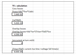
2) I calculated the efficiency and found it as below.

PgateD
(W)
Pboot
(W)
Pcond
(W)
Psw
(W)
PLMG
(W)
Pcoil
(W)
total
(W)
2.8E-03 0 4.46E-01 5.78E-01 1.03E+00 0.57 1.60E+00

This is different from the data you provided. What makes this difference?

(Example: inductor AC loss, tTR={Vin/(25 V/ns)}, etc.)

3) Could you tell us the measurement environment of the manufacturer?

Here is the equipment my customer used for measurement.

DAQ970A / DAQ973A Data Acquisition System | Keysight

I would like some comments on the difference in efficiency data.

Best Regards,

Ryusuke

  • Hi Ryusuke-san,

    1. The LMG2100EVM-078 is the EVM for the LMG2100R044. The LMG2100EVM-097 is the EVM for the LMG2100R026.

    2. I can test the efficiency of the EVM in the lab and check to make sure we are getting the same results. Can you double confirm whether they are using the LMG2100EVM-078 (LMG2100R044) or they are using the LMG2100EVM-097 (LMG2100R026)?

    3. It looks like the Keysight DAQ that is linked should be good for efficiency measurement. I usually use a Yokogawa two channel power analyzer for input and output power and average over a time period.

    Best,

    Kyle Wolf

  • Hi Kyle,

    Thank you for your comformed.

    2)I checked again.

    My customer is testing with LMG2100EVM-078 (LMG2100R044).

    Does ''the same results'' mean the same as the efficiency data of 96.27%?

    I would appreciate any comments on the difference between the formula and the efficiency value you provided.

    My customer is considering GaN FET for the first time.

    I would like to know how much efficiency you expect to improve is change from Si FET to GaN FET.

    I would appreciate your views.

    Best Regards,

    Ryusuke

  • Hi Ryusuke-san,

    I tested the LMG2100EVM-078, and measured roughly the same efficiency as the customer for the system.

    48Vin

    12Vout

    10A Iout

    300-600kHz 

    duty cycle: 25%

    Switching Frequency (kHz) Efficiency (%)
    300 96.78
    400 96.66
    500 96.34
    600 96.11

    To be able to comment on the the power loss calculations you have above, can you provide the calculations/equations you did?

    Best,

    Kyle Wolf

  • Hi Kyle,

    I'm sorry for my bad way of telling you.

    There is a difference between the calculation formula and the actual measurement result.

    Please see the calculation file below.

    LMG2100 Loss.xlsx

    My calculation formula shows a total loss of about 1.6W.

    The value calculated from TI shows 4.49W.

    1) Do you know the cause of this difference?

    2) From the calculated value of 1.6W, we can expect the power efficiency to be higher, but the measured value did not.

    I would like to hear your thoughts on what causes these.

    Best Regards,

    Ryusuke

  • Hey Ryusuke-san,

    For power loss calculations:

    • LMG2100R044
      • Conduction losses: 0.73W (you had 0.44W, this was missing the Rdson temperature coefficient)
      • Switching losses: 0.60W (you had 0.58W, this was roughly the same)
      • Deadtime losses: 0.14W (you had not included this loss)
      • gate drive loss / boostrap losses: negligible 
    • Inductor
      • You have just calculated the copper losses (conduction losses) here. inductor will core losses & eddy current losses too. It is harder to estimate these forms of losses, but is reasonable to assume that they make up a portion of the remaining losses.
    • Parasitics
      • board parasitics will contribute a small portion to the total system losses as well.

    Best,

    Kyle Wolf

  • Hi Kyle,

    Thank you for sending your opinion. I understood.

    1) Rdson is considered in terms of Max and Min values.

    2) About dead time losses, 
    Can you give me the calculation? I can't find it is included in the data sheet.

    3) Inductor core losses, eddy current losses, and board parasitic loss

    are considered to be a major factor in the difference between 4.49W and 1.6W?

    Best Regards,

    Ryusuke

  • Hey Ryusuke-san,

    1. For Rdson I used the 4.4 mohm typical value, and multiplied it by the temperature coefficient in the datasheet figure 5-6.

    2. Deadtime losses are the reverse conduction losses that occur during the deadtime. equation: deadtime(ns) * Vsd(V) * Isd(A) * 2 = deadtime losses 

    Isd is the current through the inductor during each of the deadtime periods. Vsd is found in the datasheet figure 5-5.

    3. Yes, I think the inductor core losses, eddy current losses, and board parasitic loss contributed to the difference.

    Best,

    Kyle Wolf

  • Hi Kyle,

    Thank you for the calculation method. It is helpful.

    I have an additional question.

    1) You said switching loss is 0.60W,  Is this a measurement or calculation?

    If this is measurement, please tell me how to measure it.

    If this is calculation, please tell me how to calculate it.

    2) Do you know the way to measure only LMG2100 losses?

    If you have, please tell me how to measure it.

    I would like to separate the LMG2100's losses from other losses.

    Best Regards,

    Ryusuke

  • Hey Ryusuke-san,

    1. I will reply here tomorrow with equation for calculating switching losses.

    2. It would not be feasible to measure losses only from LMG2100.

    Best,

    Kyle Wolf  

  • Hi Kyle,

    1) Thank you for your reply and look forward to it.

    2) Is XAL1010-472MED the best inductor for efficiency? (on the EVM)

    I understand that ACR cannot be understood from the data sheet.

    Do you know any inductor recommended for efficiency?

    Best Regards,

    Ryusuke

  • Hey Ryusuke,

    1. I calculated the switching losses as follows:

    • Coss loss = Vdc^2*FSW*Co(tr)   
      • Co(tr): time related Coss, this is found by integrating the Coss graph in the datasheet with respect to voltage
        • 501pF for 48V bus voltage
      • FSW: switching frequency
        • 300kHz
      • Vdc: DC voltage
        • 48V
    • Overlap loss: = Vdc * Ion * (Trise + Tfall)/2 * FSW
      • Ion: current at turn on
        • ~4A
      • Trise + Tfall: current rise time + voltage fall time (divided by two because area of triangle 1/2 Base * height) 
        • ~8ns

    2.  Inductors can be optimized based on switching frequency, bus voltage, I_L (inductor current), and desired current ripple. The XAL1010-472MED inductor may be better used at higher switching frequency. For this switching frequency try using an inductor with more inductance.

    Best,

    Kyle Wolf

  • Hi Kyle,

    I send my calculation as follows.

    5826.LMG2100 Loss.xlsx

    I calculated as follows.
    ・Coss loss =0.344W
    ・Overlap loss =0.459W
    Is the calculation correct? If it is correct, the total is 0.803W. Is this value of 0.803W switching loss?

    Best Regards,

    Ryusuke

  • Hey Ryusuke,

    I have updated the formula above, I hadn't added the divide by two to the overlap loss formula. 

    The reason the divide by two is needed is because the overlap area is roughly a triangle and the height is Vds*Ion, the base is Trise+Tfall. So the area is 1/2 *base * height.

    This fixes the switching losses and estimates them to be 0.575W 

    Best,

    Kyle Wolf 

  • Dear Kyle,

    I'm evaluating the efficiency of LMG2100R044. Thank you for your support. 

    I have some questions.

    1) where are Trise and Tfall in datasheet ?

    2) Are Trise and Tfall depend on Vdc ?

    3) The switching loss formula that you told us above and the one described in datesheet is different.  Which formula should i use ?

    Best,

    Fumiya Tanaka

  • Hey Tanaka-san,

    1. Trise & Tfall are not in the datasheet. These are simplifications/estimates to estimate the time in the overlap region during the switching transition.

    2. Yes, Trise+Tfall will be dependent on Vdc. One of the parameters that effects these is the voltage drop period of turn on, which can be estimated by Vdc/slew rate.

    3. The equation I provided breaks the switching losses into separate categories, Coss loss and overlap loss. The equation from the datasheet presents one equation to estimate switching losses. They are both different ways of estimating the switching losses.

    Best,

    Kyle Wolf

  • Hi Kyle,

    Thank you for responding so many times!

    I think your recommend ''to increase the inductance'' is because to reduce the inductor ripple current.

    Should it be about 4.7uH→10uH?

    I would appreciate any comments.

    Best Regards,

    Ryusuke

  • Hey Ryusuke-san,

    The 10uH inductor will decrease the winding/conduction losses in the inductor. When I was testing the efficiency of the EVM for the above test, the inductor was the hottest part so I think this will help system efficiency.

    The higher inductance will reduce the current ripple in the inductor which will then cause the inductor to have less conduction losses (less current ripple means less RMS current). The turn-on current of the hard switching FET will increase so the Coss losses in the FET will increase. The size of the inductance in the inductor will be a balance losses here.

    Best,

    Kyle Wolf