Tool/software:
Hello to all.
I working on a new design ordinary 100W LLC, running at a quite high frequencies. For now I built new prototype based on UCC256601DDBR, working at quite low frequency
Design fed by 380VDC bus.
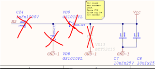
Input stage with filter, as well as the secondary side, are not shown, but I can attach it on a request, if someone will be interested.
The problem, design doesn't start at all.
No one pulse at the LO pin, which in turn will allow Cboot to be charged.
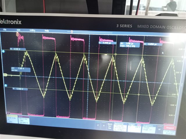
Here is the list of abnormal behaviour moments, I try to present:
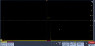
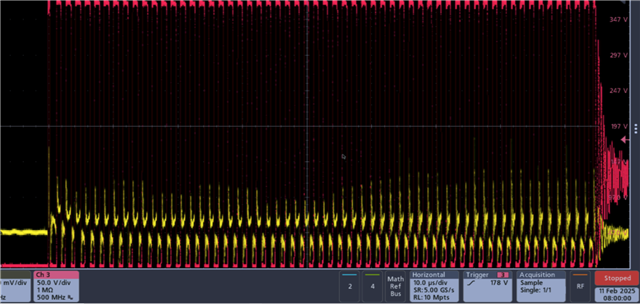
a) no one pulse at the LO pin (capturing with trigger in "single" mode).
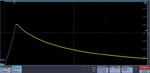
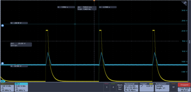
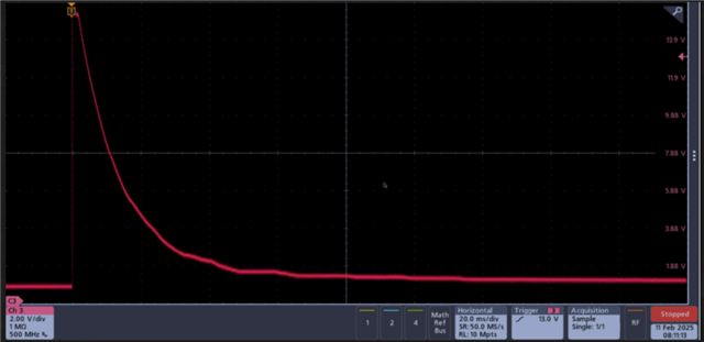
b) VCCP pin voltage stays at VccreststartJfet almost all the time, in certain samples, each second, it starts to rise till Vccstartsself (monotonously), then decays back to VccrestartJfet (monotonously). (please see screenshot PIN 12).
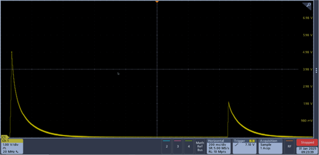
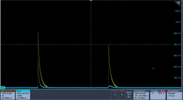
c) V5P in certain cases reaches 5V (immediately or doing some amount of attempts) then stays at 5V. In certain cases, it stands up to 5V, stays some ms then falls down. (please, see attached screenshot PIN8)
d) OVP/OTP pin always 0V(the internal current source doesn't activate), despite there is no short circuit at the pin.
What I have found, Tset divider upper value imposes serious impact on the V5P behaviour, despite specified Vccp 10mA current capability during the start-up.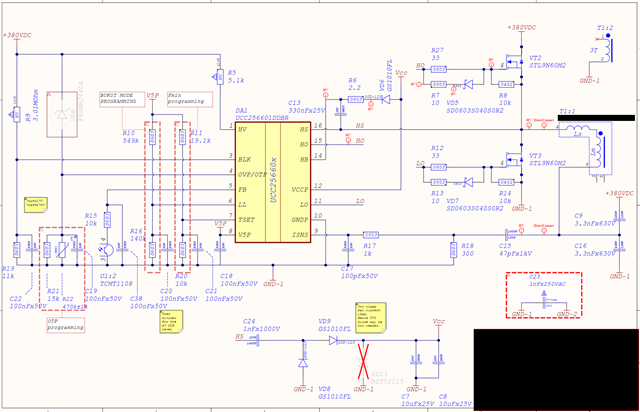
PIN 8: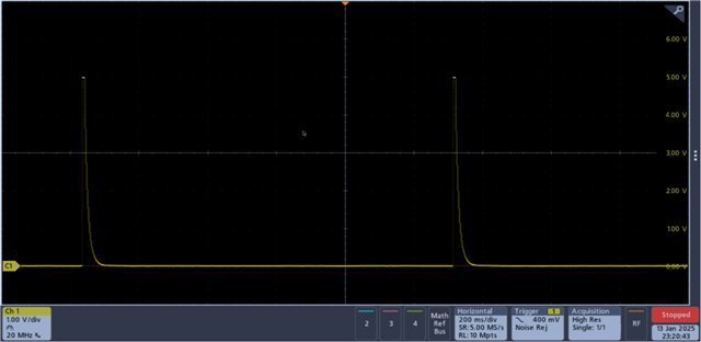
PIN 12: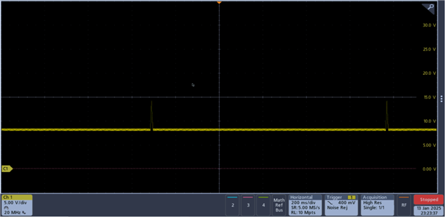
I tried to completely short ISNS pin to the GND, to avoid possible spurious CS protection triggering, but no effect.
I'll would like to ask you to check my design, hint me, what can be wrong.
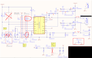
Please, find complete power stage schematic attached as a PDF
UCC256601DDBR 100W LLC.pdf