This thread has been locked.

If you have a related question, please click the "Ask a related question" button in the top right corner. The newly created question will be automatically linked to this question.

TPS274C65EVM: Could not drive TPS274C65EVM - Is chip rejecting register setting?

Part Number: TPS274C65EVM
Other Parts Discussed in Thread: TPS274C65,

Tool/software:

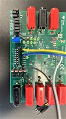
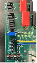
We have two different setups to evaluate TPS274C65. 

#1. TPS274C65EVM-USB board

2. SPI TPS274C65EVM board

Both are connected to the same Arduino setup. They use 100% the same code and drive with the same Arduino. Both are on TPS274C65 address 05 (B0 for write).  

The first setup works fine, we can set LED 1_4 and 5_8 on/off, and set the output channels open/close (enable/disable). We are running heaters don't he output channels. We can see heaters turn on/off as expected. Plus can configure current limits fine. 

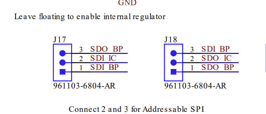
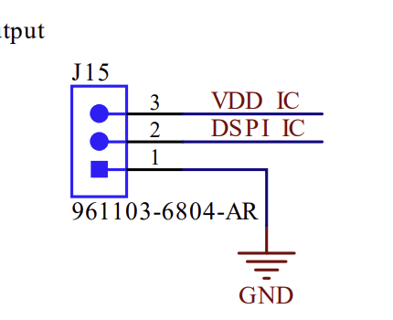
However, setup two does not do anything. We can see SPI responses, but nothing happens on the board. We can't enable or disable LEDs or get current on the output channels. We believe dip switches are fine. We have used both internal buck converters, disabled buck, and external VDD, but we are not going anywhere. 

Thanks,

Jamil 

  • Jamil,

    Thank you for the email.

    For the USB EVM, by default is is configured to work in addressable SPI mode. The idea with this EVM is that it is there are 2x TPS274C65 devices on the board with separate chip addresses (configured by the address pins), and part of the SPI frame itself is the address of the specific chip you want to configure:

    The USB EVM is meant to be more of an out-of-box solution where you can use the USB MCU on the board to easily program it without having to syphon out the SPI lines (although there would be no harm here).

    The regular non-USB EVM is meant to be able to work in all different configurations: addressable SPI, daisy chain SPI, and standalone. If the USB EVM is working with your Pi and the regular EVM is not, this makes me think that maybe the regular EVM's jumper configuration might not be setup correctly to match the SPI frame that you are sending from your PI. Could you send a closeup of the jumper/dip switch configuration of the non-USB EVM? It's possible if you are using addressable SPI that the address might be mismatched. 

    Best Regards,
    Tim

  • Thanks, Tim. For the replay. I understand your explanation as documented in the EVM manual. We believe we have the correct dip switches. I have attached a picture of the EVM showing the dip switch and jumper settings. Can you have a look and let me know why you think it may have an incorrect address? 

    To be safe, we have tried our code in the loop to all configurable addresses. 

  • Jamil,

    Apologies for the delay. A couple of different things to try here:

    Could you unpopulate those jumpers and just tap into pin 2 for your MOSI and MISO lines? 

    Since you are cycling addresses I a going to make an assumption that the address configuration is not an issue.

    It's hard to see explicitly from the picture, but could you verify J15 is set to 1-2 position (enabling addressable SPI)?

    Best Regards,
    Tim

  • J17 and J18 were already as you have described. However, fixing J15  fixed the issue. SPI EVM board does work now.

     However, “TPS274C65 Evaluation Module SLVUCI0 – MAY 2022”  documents say to connect 2-3:


    Now our main issue is getting it to work with AM243EVM. My second thread is about that:

    https://e2e.ti.com/support/power-management-group/power-management/f/power-management-forum/1461789/tps274c65evm-develop-driver-for-tps274-on-am243xevm-module

  • Thanks Jamil,

    I will close out this thread and we will follow-up on the referenced thread. I will put a note in to correct the EVM datasheet.

    Best Regards,
    Tim