This thread has been locked.

If you have a related question, please click the "Ask a related question" button in the top right corner. The newly created question will be automatically linked to this question.

UCC28951-Q1: Duty cycle adjustments at lower loads.

Part Number: UCC28951-Q1

Tool/software:

Hello mike.

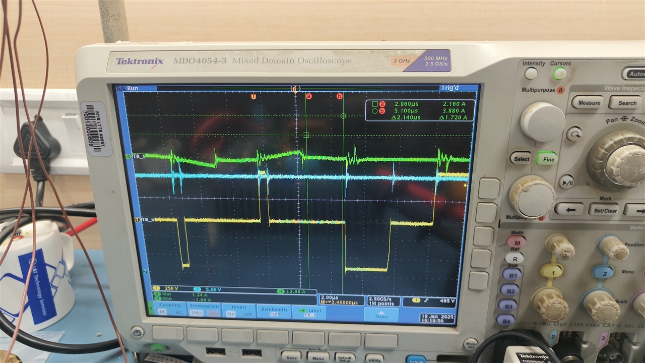
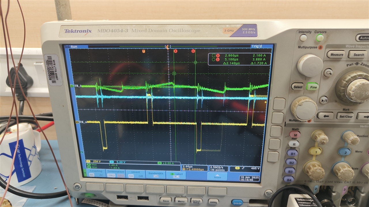
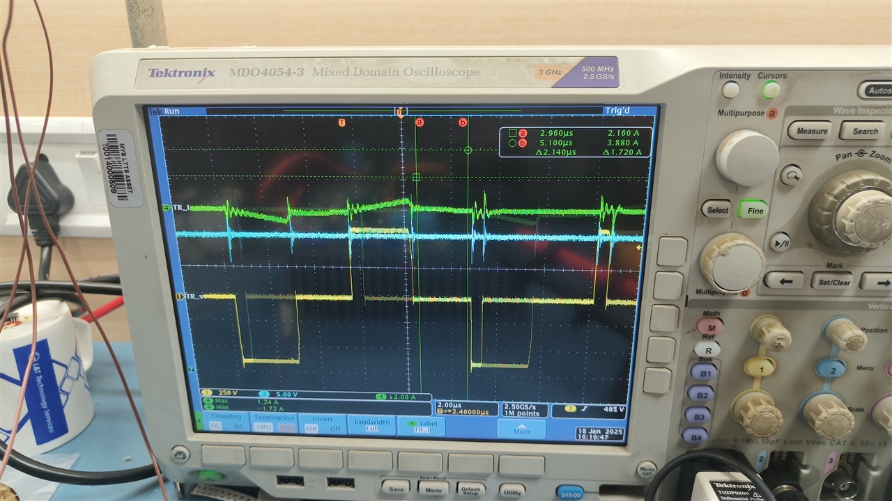
I'm trying to adjust compensation and TMin values and have bought the board to this stage. Below I'm attaching waveforms and videos.

This is higher voltage lower loads currents.

Vin : 600V, ILoad : 2A.

I still have to go higher voltage upto Vin : 975vDC. 

Are these waveforms correct or is this acceptable behaviour??

  • Hello,


    This is not normal and does not have to do with your tmin setting.  It looks like you duty cycle is jumping from 10% to maximum.


    If your load is steady state and the design is doing this you have one of the following 2 issues.

    1. Your CS signal is reacting to noise.

    2. Your voltage loop is unstable


    By studying CS, amplifier output and your transformer input you should be able to determine which or both of these issues.


    You had the design working and moved the bulk capacitor.  The design at this time did not have an issue.  This might have something to do with it as well.

    I would compare your original design to this one.  Moving the bulk capacitor could be putting more noise on your CS signal.


    Regards,