This thread has been locked.

If you have a related question, please click the "Ask a related question" button in the top right corner. The newly created question will be automatically linked to this question.

LMZM23601: Way to maintain PFM

Part Number: LMZM23601
Other Parts Discussed in Thread: LMR60410, TPSM33615, ,

Tool/software:

Hi support team,

When the output voltage is 8V and the input voltage is 9.5V, the PFM operation switches to PWM operation.
This causes the input current to increase from 400uA (in PFM) to 5mA (in PWM).
(The load current is expected to be extremely small.)
If the input voltage is 9.6V, it remains in PFM and maintains 400uA.

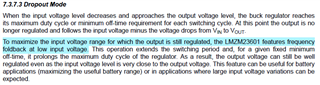
The LMZM23601SILR does not allow adjustment of the internal frequency, so I don't think it is possible to adjust the inductor valley current.
Therefore, I think it is impossible to control the switching between PFM and PWM.

I am looking for a way to maintain PFM.
To control the switching between PFM and PWM, is it necessary to choose the TPSM33615RDNR, which allows internal frequency adjustment, or the LMR60410 with an external inductor?

Regards,
Dice-K

  • Hi Dice-K,

    Could you please let me know what is your load current? 

    For more information regarding use of TPSM33615 in PFM, please refer to the e2e thread - TPSM33615: Conditions for switching to PFM - Power management forum - Power management - TI E2E support forums.

    For LMR60410, frequency can be adjusted by placing a resistor between the RT pin and PGND. To select PFM mode, MODE/SYNC pin should be tied to ground. For more details, please refer to device datasheet.

    Regards

    Arpita

  • Hi Arpita,
    Thank you for your reply.

    The load current is expected to be less than 1mA.
    Is it correct to assume that the LMZM23601 cannot adjust the inductor valley current?

    Best regards,
    Dice-K

  • Hi Arpita,

    Thinking about it again, it seems that "frequency foldback" may be occurring because the input voltage is approaching the output voltage.

    When "frequency foldback" occurs, will the converter switch from PFM to PWM even at light load?

    Best regards,
    Dice-K

  • Hi Dice-K

    Could you please provide waveforms of Vout, I out, Iin, Vin during the transition? Also, please me know the exact value of load current.

    Regards

    Arpita

  • Hi Arpita,
    Thank you for your support.

    I tested it with LMZM23601EVM.

    LMZM23601_SW.xlsx
    When VIN approached VOUT, the switching waveforms of AUTO and FPWM became the same, even at a light load of IOUT = 40mA.
    Is it correct that the light load mode is disabled when VIN approaches VOUT?

    Best regards,
    Dice-K

  • Hi Dice-K,

    I see both the waveforms have taken with Vin=10V?

    As you said, you are observing switching from AUTO mode to FPWM mode as Vin approaches Vout, can you mention exactly at what Vin you observed the transition? Please confirm whether the MODE/SYNC is grounded.

    Regards

    Arpita

  • Hi Arpita,
    Thank you for your reply.

    VIN is written above each waveform.
    MODE/SYNC is set with a jumper switch.
    Would you please check the operation with the LMZM23601EVM?

    Best regards,
    Dice-K

  • Hi Dice-K,

    Both the waveforms Vin is written as 10V, as I mentioned previously. But you mentioned previously you are observing the shift automatically from Auto mode to FPWM even at 40mA load current as you are changing Vin. Could you please clarify this? Also, please confirm how the MODE/SYNC is set with a jumper switch (is it shorted to Vin or GND)?

    I will order the EVM and check the operation. This might take couple of weeks. Please expect a delay. I will get back to you after getting the results.

  • Hi Arpita,
    Thank you for your reply.

    The input voltage for each waveform is as follows.
    Top row : VIN=10V
    Middle row : VIN=6.5V
    Bottom row : VIN=5.3V


    The MODE/SYNC pin setting is set in "Mode Options" below.
    www.ti.com/.../snvu578a.pdf

    I look forward to receiving the result of your EVM evaluation.

    Best regards,
    Dice-K

  • Hi Dice-K, 

    Thank you for the clear explanation. I have ordered the EVM. I will get back to you with results.

    Regards

    Arpita

  • Hi Dice-K,

    I have tested and confirmed the behavior in the EVM. 

    As Vin reduces nearly to Vout> initially Vout starts falling as the internal Error amplifier initially tries to maintain previous duty > COMP increases> COMP min threshold is crossed, and thus the mode shifts to FPWM, even at very light load.

    As for your application, input is ~9.5-9.6V, and Vout=8V; You can use TI LDOs for low-drop-out applications.

    Regards

    Arpita