This thread has been locked.

If you have a related question, please click the "Ask a related question" button in the top right corner. The newly created question will be automatically linked to this question.

BQ76952: BQ76952 interfacing with NXP's S32K144 MCU

Part Number: BQ76952

Tool/software:

Hi team,

We are interfacing BQ76952 AFE with NXP's S32K144 MCU using I2C interface.

We got the BQ76952 example driver code from the following link:

https://www.ti.com/tool/download/SLUC701.

The example code available only for TI's MSP430 and STM32 micro controllers.

In order to support the S32K144 MCU, we converted the STM32 sample code into NXP code.

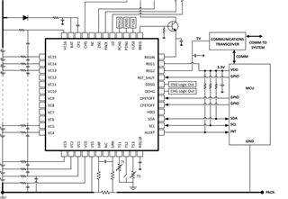
We connected the following pins from the AFE to S32K144 MCU:

DFETOFF  -  GPIO OUTPUT

RST_SHUT - GPIO OUTPUT

ALERT  -  GPIO INPUT

REG1 - 3.3V

SDA - LPI2C_SDA

SCL - LPI2C_SCL

However, we are not able to read the cell voltages from the AFE.

Please assist me in fixing this problem.

Best regards,

Hareesh

  • Hello Hareesh,

    Do you mind sharing if there were any errors the code gave back? Also, when you are saying unable to read the cell voltages from the AFE, can you still communicate with the AFE at all?

    Best Regards,
    Alexis

  • Hi Alexis,

    Thanks for the reply.

    Do you mind sharing if there were any errors the code gave back?

    No, we are not getting any errors.

    Also, when you are saying unable to read the cell voltages from the AFE, can you still communicate with the AFE at all?

    No, we are not able to communicate with the AFE.

    Best regards,

    Hareesh

  • Hello Hareesh,

    Do you mind sharing a schematic of your connections?

    When you said you connected REG1 to 3.3V, are you supplying 3.3V to REG1?

    Also, do the SDA and SCL lines have pullups to REG1 or 3.3V?

    Best Regards,
    Alexis

  • Hi Alexis,

    Do you mind sharing a schematic of your connections?

    We connected the circuit as shown in below, which we got from the BQ76952 data sheet.


    When you said you connected REG1 to 3.3V, are you supplying 3.3V to REG1?

    Yes, we are giving 3.3V to REG1 from the MCU.

    Also, do the SDA and SCL lines have pullups to REG1 or 3.3V?

    The pullups (10kohm each) are already linked to 5.0V from the MCU side.

    Best regards,

    Hareesh

  • Hello Hareesh,

    Yes, we are giving 3.3V to REG1 from the MCU.

    Thanks for clarifying. REG1 is an LDO that can output voltages at various levels, so you would not need to supply 3.3V from the MCU to it. 

    The pullups (10kohm each) are already linked to 5.0V from the MCU side.

    Thanks for confirming this. Could you share any logic analyzer files of the SCL/SDA lines when you try to communicate? What commands/subcommands are you sending? Also, what is the voltage of REG18 and RST_SHUT as you try to communicate with the part as well?

    Best Regards,
    Alexis

  • Hi Alexis,

    what is the voltage of REG18 and RST_SHUT as you try to communicate with the part as well?

    The voltages at pin:

    REG18 - 3.8V

    RST_SHUT - 0V

    REG1 - 3.3V

    Could you share any logic analyzer files of the SCL/SDA lines when you try to communicate?

    Kindly find the attached file for SCL and SDA signal captures.

    SCL_SDA_signals.rar

    What commands/subcommands are you sending?

    Please find the following code:

    	CommandSubcommands(BQ769x2_RESET);  // Resets the BQ769x2 registers
    	Delayus(60000);
    	BQ769x2_Init();  // Configure all of the BQ769x2 register settings
    	Delayus(10000);
    	CommandSubcommands(FET_ENABLE); // Enable the CHG and DSG FETs
    	Delayus(10000);
    	CommandSubcommands(SLEEP_DISABLE); // Sleep mode is enabled by default. For this example, Sleep is disabled to demonstrate full-speed measurements in Normal mode.

    Best regards,

    Hareesh

  • Hello Hareesh,

    REG18’s voltage is above the abs max of 2V. This can potentially occur when there is a GPIO that is connected to a higher voltage and is configured to be connected internally to REG18.

    Do you mind sharing your schematic? If you would like it to be private, you can DM it to me.

    Also, somethings to note:
    1. Does your MCU support clock stretching? If the MCU does not support clock stretching, the device will not be able to properly communicate.
    2. What is the I2C device address of the BQ769x2 family?

    Best Regards,
    Alexis

  • Hi Alexis,

    Do you mind sharing your schematic?

    We are referring the following reference design which was mentioned in the BQ65952 data sheet.

    We connected the following pins between the MCU and the BQ7695202 AFE based on the reference design:

    DFETOFF

    RST_SHUT

    ALERT

    SDA

    SCL

    GND.

    Please advise whether there are any pins I should connect in order to read the AFE's cell voltages.

    1. Does your MCU support clock stretching?

    Yes, the MCU will support the clock stretching.

    We are giving the I2C device address as 0x10.

    Best regards,

    Hareesh

  • Hello Hareesh,

    Were you able to communicate before any configuration changes were made or did communication stop after configuration changes were made?

    Are you driving voltages to the DFETOFF/ALERT pins or any other pins of the AFE?

    There shouldn’t be any other pins that need to be connected to read the AFE’s cell voltages if SCL/SDA are connected properly to communicate with the device and the cells are attached. 

    Since you can’t communicate with the device, you aren’t going to be able to read the cell voltages. I’m trying to determine where/when this communication issue occurred.

    REG18 shouldn’t be reading 3.8V, so it would be good to determine how it’s going so high.

    Best Regards,
    Alexis

  • Hi Alexis, 

    My issue is resolved.

    I just changed the I2C device address from 0x10 to 0x08, and the AFE is now able to communicate.

    I appreciate your assistance..

    Best regards,

    Hareesh