This thread has been locked.

If you have a related question, please click the "Ask a related question" button in the top right corner. The newly created question will be automatically linked to this question.

BQ24133: Requesting a review of the BQ24133RGYR circuit.

Part Number: BQ24133

Tool/software:

Hello,
I hope you're doing well. I have a few requests and questions to share with you.

Request #1

BQ24133_CHARGE CIRCUIT.pdf

I am designing a circuit using the BQ24133, and I would like you to review it.
The power specifications are as follows:

  1. Input power (adapter specs): 5V / 3A
  2. Expected system load current consumption: Approximately 1A
  3. Battery specs: 18650 / 1S1P / 3000mAh

The BQ24133 settings are configured as follows:

  1. FAST CHARGE: 1A
  2. AC SET: 2A
  3. OVP SET: 6V
  4. CELL SELECTION: 1 CELL
  5. SAFETY TIMER & TERMINATION CURRENT
    • TIMER: OFF
    • TERMINATION: ON

Question #1

  • Does the BQ24133 generate a significant amount of heat?
  • How is heat typically managed in this device?

Question #2

  • With an input voltage of 5V, what will the voltage be for the system load?
  • Is there any noticeable voltage drop?

Question #3

  • The input power (adapter specs) is 5V / 3A.
  • The INPUT CURRENT REGULATION SETTING is set to 2A.
  • Will there be any issues if the adapter's current rating exceeds the setting?

This is my first time using this device, so I appreciate your understanding of the numerous requests and questions.
Looking forward to your response.

Thank you, and have a great day!
JIHOON.

  • Hello,

    We were out off office on Monday 1/20, response may be delayed. Thank you for your patience

    Best Regards,

    Christian.

  • Hello Jihoon,

    Schematic Review:

    200uF of capacitance on input is a lot, I'm not sure why this was added.

    R19/R45 should be 4.02k not 402k

    I don't see any other obvious issue,

    • Does the BQ24133 generate a significant amount of heat?
    • How is heat typically managed in this device?

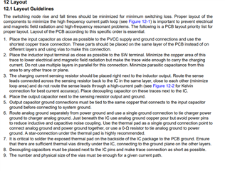
    I would recommend following the Layout guidelines in the datasheet for the best way to reduce heat to the IC.It is critical to solder the exposed thermal pad on the backside of the IC package to the PCB ground. Ensure that there are sufficient thermal vias directly under the IC, connecting to the ground plane on the other layers.

    • With an input voltage of 5V, what will the voltage be for the system load?
    • Is there any noticeable voltage drop?

    If the adapter is present the system load should be close to the same value as adapter voltage. There should not be a noticeable voltage drop. 

    • The input power (adapter specs) is 5V / 3A.
    • The INPUT CURRENT REGULATION SETTING is set to 2A.
    • Will there be any issues if the adapter's current rating exceeds the setting?

    No, The adapter should not exceed the set 2A.

    Best Regards,

    Christian