This thread has been locked.

If you have a related question, please click the "Ask a related question" button in the top right corner. The newly created question will be automatically linked to this question.

TPS548D22: FSEL RAMP Select Setting for 5Vin

Part Number: TPS548D22

Tool/software:

Hi Sir, 

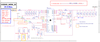
I have a Design Spec 

Vin =5V, Vout=1.1V, Iout=30A, the FSEL PR231 is setting 90k9

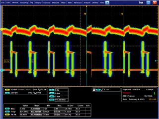
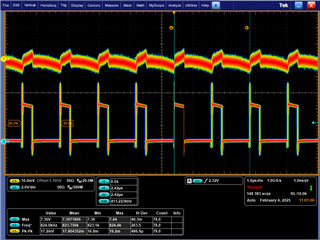
the switch frequecy is unstable at havey load, it look like sub-hamonic Osclliate ?

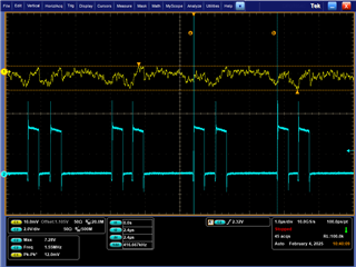
I adjust the resistance PR231 to 75k, 60k9 and 47k5 , the switch frequency is stable , but with the different jetter level. 

Could you provide the formula to calculate this case. thanks.  

(from up to down, 75k, 60k9, 47k5)

  • Hello,

    A response will be posted this week.

    Thanks,

    Calan

  •  

    The internal RC ramp generator inside the TPS548D22 works with the inductor to create a RSP to IL forward transconductance of:

    GM = 8 x RC / L 

    The RC values for various selections of FSEL are given in table 7 - https://www.ti.com/lit/ds/symlink/tps548d22.pdf#page=25 

    FSEL = 90.9kΩ selects Fsw = 875kHz and Ramp R x 3 (34.4μs).  With a 150nH inductor, this produces an RSP to IL transconductance of 1,835S

    To ensure stability, there needs to be sufficient output capacitance so that (Vrsp / Vout) x GM x Zout(f) < 1 at about 200kHz for an 875kHz switching frequency.

    Your Vout = Vrsp (no feedback divider) so that translates to a Zout(200kHz) < 545μΩ

    WIth two polymer capacitor with ESR = 9mΩ (combined 4.5mΩ) the ceramic capacitors would need an impedance of 620μΩ at 200kHz, which would require about 1,300μF.   That is why you are seeing instability of the switching frequency with only 5x 47μF ceramic capacitors.

    Changing to 75kΩ reduces the time-constant from 34.4μs to 20μs, which reduces the forward transconductance to 1067S, which only needs a ceramic capacitor Zout(f) of 1.18mΩ, which is about 670μF of capacitance.  This is stable, but the margin is lower than we would typically recommend.

    Changing to 60.9kΩ reduces the time constant to 10.4μs, which reduces the forward transconductance to 555S, which only needs 3mΩ from the ceramic capacitors, or about 265μF and is clearly showing stable switching frequency.

  • Hi Peter, 

    Thanks for your explain,

    I think intuitively , that Rset 90.9k-> 60.9k , RC generater 's R reduce, so the Time constant reduce,  RAMP compensation inject faster signal to RSP 

    But I still confuse abuot 60k9 and 47k5,  which one is better at stable and transient performance ? 

    Could you analysis it. thanks.

  •  

    Transient Performance:

    Small signal transient performance will track 1/GM.  A higher GM will produce lower output voltage deflection (under / overshoot) for the same transient load change.

    the R x 3 ramp with the highest ramp time constant (lowest ramp amplitude) will produce the highest GM and the best small signal transient performance

    The R x 2 ramp will be next, followed by R x 1 and R / 2 as the ramp amplitude gets higher and the GM gets lower.

    Since the GM equation is linear with the ramp time-constant, the expected output voltage change on a load-step is inversely proportional to the time constant.

    Changing the time constant from 20μs to 10.4μs will increase the expected output voltage deflection (undershoot or overshoot) by 20/10.4 = 1.92 or 92%

    You can use the GM equation I provided to estimate the output voltage change for a sudden load step by ΔVout ≅ ΔIout / GM 

    This does not account for the non-linear large-signal response that may result in a larger overshoot during sudden load-drop which is caused the control loop's inability to create a negative duty cycle, which created a lower-bound on the overshoot response that depends on Vout, ΔIout, L, and Cout.

    Stability:

    Loop stability is generally comparable for all loops where the GM x Zout(f) = 1 frequency is greater than 30kHz (this is specific to the TPS548D22 implementation) and less than 1/4 of the switching frequency (this is general for D-CAP3 Constant On-time Control)

    Note:  This assumes local sensing of Vout at capacitors located close to the inductor.  Additional inductance in the power path, especially when combined with remote sensing of Vout and remote capacitance at the remote sense point for input bypassing of whatever the TPS548D22 is powering can decrease the maximum stable frequency below Fsw/4.

    Jitter Performance

    Pulse Frequency Jitter will be reduced as the ramp amplitude and slew-rate increases, so loops with lower time-constants will produce less pulse frequency jitter.