This thread has been locked.

If you have a related question, please click the "Ask a related question" button in the top right corner. The newly created question will be automatically linked to this question.

BQ76952: Bringing up a 13S battery pack

Part Number: BQ76952
Other Parts Discussed in Thread: BQSTUDIO, EV2400

Tool/software:

Hi,

We made a custom board using the BQ76952 for a 13S battery pack. I am trying to bring it up and test whether it works. 

I initially tried the step mentioned in the EVM User Guide. Where I powered using a lab-bench power supply. Provided  32V - 48V on the 13S+ cell connection and 0V (GND) on the BAT- pin. I was expecting 32-48V on the PACK+ and PACK- pins. But unfortunately, it was 0V. Not sure if something is wrong? I didn't have anything connected on the other cell connections.

I'm attaching the schematic of our board, if you notice anything off? I followed the 2-layer reference design provided in the BQ76952 reference design section.

How would I go about testing this board? If you have any suggestions?

Thanks again for all your help.

13S_BatteryPack.pdf

  • Hello Mo,

    Did you enable the FETs with FET_EN as well? This will allow the FETs to turn ON.

    Please give me some time to review your schematic.

    Best Regards,
    Alexis

  • Hi Alexis, I didn't turn them ON. Do I need to program the board to turn it on?

    I was hoping the default functionality, like the PACK+, PACK- voltage and COV, SCD would be available when turning on? Please correct me if I'm wrong.

  • Hello Mo,

    Step 11 of Section 2.2 Quick Start in the EVM User Guide mentions to click the FET_EN button on the Commands panel, which enables the FETs. By default, the FETs are OFF.

    Best Regards,
    Alexis

  • Hi Alexis,

    Thank you for pointing that out. I misunderstood, thinking the design would work out of the box.

    In reference to my design (referring to the schematic I shared earlier), can I connect the SCL, SDA pins of the I2C bus to a USB-I2C converter and try reading it through a windows PC running the BQStudio?

    Further, in order for I2C to work with BQStudio, do I need to provide any additional power to the board, apart from the power I provided below:

    Provided  32V - 48V on the 13S+ cell connection and 0V (GND) on the BAT- pin
  • Hi Alexis,

    Further to my previous message, can the BQStudio work with generic USB-to-I2C adapters and communicated with our custom board (using the BQ76952). Or it needs the EV2400 communication adapter, as a mandatory requirement?

    On another note. I know you are working on reviewing my schematic. Just checking to see if you happen to notice anything off on it.

    Thanks again.

  • Hi Alexis,

    Just trying to verify the BMS as soon as I can. In order to send it out for production. Please pardon my consecutive messaging.

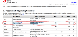
    I noticed this max requirement of 12V on the BAT pin during OTP. I don't know how one could ensure that? Our board is designed for a 13P configuration and it'll go up to 54V at the least, during OTP. Please advise if I understood this incorrectly.

    On another note. It looks like the BMS can be programmed using a STM32 MCU. I'm trying it out. The idea is to connect all the 13 cells, followed by, SCL, SDA and GND pins between the STM32 MCU and the BQ76952. Please advise if you think I'm missing any step?

  • Hello Mo,

    Apologies for the wait and thank you for your patience.

    The schematic looks fine to me so far.

    While you could use a USB-I2C converter to connect it to a PC, you would need an EV2400 to use with bqStudio. The EVM comes with a MCU programmed with the EV2400 firmware to use with bqStudio. You could also use an external MCU to program the device, however, you would not have access to bqStudio.

    We have some sample code you can use for the STM32 MCU as well you can reference.

    Please follow Section 3 OTP Programming from the Calibration and OTP Programming Guide we have.

    The idea is to connect all the 13 cells, followed by, SCL, SDA and GND pins between the STM32 MCU and the BQ76952

    That sounds fine. The EVM User Guide shows a schematic of how the MCU is connected to SCL/SDA and our AFE as well if you want another point to reference.

    Best Regards,
    Alexis

  • Hi Alexis,

    Thank you so much for verifying and clarifying lot of things for me. Appreciate all the help.

    I had a quick question in regards to validating if the PCB assembly went good (this is even before I do the I2C programming). Is there a test (like voltage measurement) I can do, in order to ensure the PCB is good to work with? For example, one thought was to measure the voltage on REG18 pin. I'm hoping it should be 1.8V if things were correct? Any suggestions?

    Thanks again.

  • Hi Alexis,

    I was able to get the battery up and running and connect it through the EV2400.

    Had a quick few questions:

    Is Vcell Mode, in my case (13S) = 0xC7FF ?

    My questions are that of a novice. But I appreciate you taking the time to walk me through my hurdles.

    Thanks again.

  • Hello Mo,

    Thank you for your patience!

    Is there a test (like voltage measurement) I can do, in order to ensure the PCB is good to work with?

    We do not have a specific test/procedure we use to ‘validate’ the PCB assembly is good to work with. As users have different design specifications, they will test to see if it is working as they expect it to.

    For example, one thought was to measure the voltage on REG18 pin. I'm hoping it should be 1.8V if things were correct?

    The voltage on REG18 will help let you know if the device is fully SHUTDOWN or not. If it isn’t showing 1.8V when it turns ON normally, that would be a concern, however, it doesn’t tell what is specifically wrong either.

    Any suggestions?

    Perhaps following the EVM User Guide can assist in what things you can evaluate for as well.

    Is Vcell Mode, in my case (13S) = 0xC7FF ?

    I believe it should be 0x87FF as you have cells 15, 14, 13, and 12 shorted together. 

    Best Regards,
    Alexis

  • Alexis, you are the best. I appreciate all the help you have provided.

    We were able to get the battery running and respond to the registers appropriately. 

    I do have a question regarding cell-balancing. For which, I'll probably create a different post.

    Thanks again.

  • Hello Mo,

    I'm glad I was able to help! As per your previous post regarding Vcell Mode, it should be 0x8FFF. 

    Best Regards,
    Alexis

  • Yup. Thank you for confirming that. Appreciate it.