This thread has been locked.

If you have a related question, please click the "Ask a related question" button in the top right corner. The newly created question will be automatically linked to this question.

UCC28740: The auxiliary power supply design issue for UCC28740

Part Number: UCC28740
Other Parts Discussed in Thread: TIDA-00702

Tool/software:

Hi,

We has a new design for the auxiliary power supply, and our spec. for below:

1. We need to auxiliary power supply output is 24V/3.3A(fully loaded);

2. The output use the synchronous rectification UCC24612-1DBVR solution, the QR Flyback solution use the UCC28740DR+CS6N120( 6A1200V MOSFET);

Our issue is the below:

1. The switch frequecy is still work on 43K-55KHz when the fully loaded(3.0A+0.3A), and the MOSFET will be enabled at several waveform valleys, we can not increase the switch frequency,

2. Half Load/ Light load, the switch frequency will be 20K-30KHz, we can hear the Inductive whistling sound;

3. The efficiency is about 87%, and the EVM is more than 90%;

Our support need:

1. We need to Increase the switch frequency to 50K~55KHz and the MOSFET will be enable on the first waveform valleys;

2. How to modify our design that we can limit the switch frequency more than 30KHz if it is on different load;

3. We test design based on the TIDA-00702 EVM: R28 to 200K, R30 to 10-20K and there are no improve:

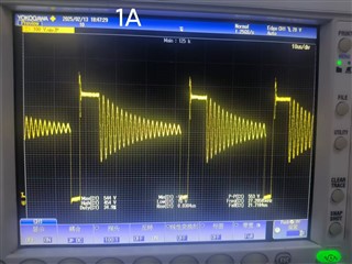
We test the waveform for your evaluated:

1. Vds waveform:

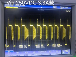
2. Vin=250VDC, output current=3.3A:
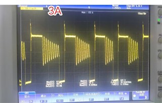
3. Vin=310VDC

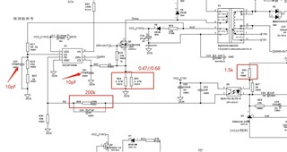
The transformer file and schematic diagram please refer to below

2437.PQ3220P12M420U.pdf

01_Power_75W24V22.pdf

  • Hello,


    1. Your magnetizing inductance of your transformer and the controlled peak current will control the frequency. To increase your switching frequency, you need to use a transformer with lower a magnetizing inductance.
      1. The following link will bring you to an excel design that can be used to calculate the magnetizing inductance for a higher frequency; as well as, the correct turns ratio for your design. https://www.ti.com/tool/download/SLUC487


    1. There is not a way to limit the frequency so the converter switches greater than 30 kHz. This device uses peak current mode and frequency modulation to control the duty cycle.
      1. You should be able to attenuate the affect of audible by increasing the switching frequency. Typically, these designs are done for a full load frequency of 75 to 80 kHz.
        1. If you design in this way as the load decrease the peak current and frequency will decrease.
        2. When the converter operates at below 32 kHz, the peak current will be controlled to ¼ the maximum. This means less energy to generate audible noise when the frequency is below 25 to 20 kHz.
    • You might want to varnish the magnetics as well to reduce audible noise.


    1. If your transformer magnetizing inductance is not correct adjusting resistors will not set the timing.
      1. Once you redesign your transformer use the following link to check and modify your design for a high frequency. https://www.ti.com/tool/download/SLUC487


    Thank you for interest in Texas Instruments (TI) products.  If you have a related question, please click the "Ask a related question" button in the top right corner. The newly created question will be automatically linked to this question.


    Regards,