This thread has been locked.

If you have a related question, please click the "Ask a related question" button in the top right corner. The newly created question will be automatically linked to this question.

BQ25750: Auto reverse mode setup

Part Number: BQ25750
Other Parts Discussed in Thread: , TPS4800-Q1, LM7480, BQ25756

Tool/software:

Hello TI team,

In my use case, I have problem related Auto-rever mode.

<Test setup>

VAC : Power supply 48V

VBAT : Battery (48V~58Vmax)

VAC_UV_level : 45V (HW resistor setting)

Disable Reverse mode

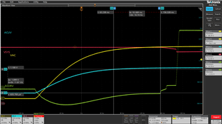
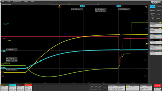
- The purpose of this test is to find auto-reverse voltage level to minimize the voltage dip when VAC is turned off and VBAT is switched on with 1A load condition. So I set the UV level is 45V.

But in this case, the charger doesn't charge and raises the VAC_DPM flag. so I set the UV level is 36V, It can charge.

Q1. What is the VAC_DPM HW level? it was register default set(4.2V).

Q2. Why is the charger raises the VAC_DPM flag not VAC_UV?

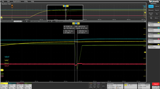
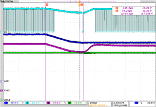
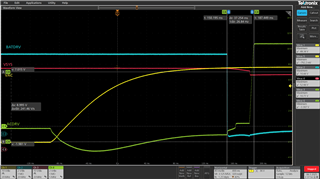
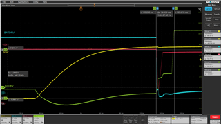
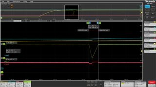
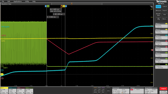
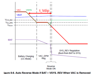
Q3. I want to minimize(t_Vdip) the voltage dip when changing VAC to VBAT with 1A system load. As attahc figure, the voltage level touched 10V. This may trigger under-voltage protection in connected systems.

Do you have any idea for that?

Left : VAC(48V) --> VBAT(55V)

Right : VBAT(55V) --> VAC(48V)

- load is 50W(1A condition)

Thank you in advance.

  • Hello Ben,

    Thanks for working on this.

    Q1 and Q2: The trigger to enter into auto reverse mode is based of the ACUV and ACOV pin voltages. Is the 36V UV level set by the registers or resistors?

    Q3: I'd recommend setting the ACUV resistor value to about 45V. I would also recommend trying to set SYSREV_UV=1 to see if that has any effect on the auto reverse switchover.

    Let me know if you have any questions about this. Let me know about the ACUV and ACOV resistor settings as well.

    Best Regards,
    Ethan Galloway

  • Hello Ethan,

    Q1, Q2 : the 45V UV level is set by the resistors. the IC registers settings are default except for the charge current setting.

    Q3 : I set SYSREV_UV=1, but I got the same result.

    Please refer to the attahced registers file.

    Registors

    AC OV&UV resistors setup

    - R_AC1 : 1000Kohm

    - R_AC2 : 10kohm(for 36V UV level) or 4.99kohm(for 45V UV level)

    - R_AC3 : 20kohm

    To clarify the question, I have two problems.

    1. When I set 45V UV level, Charger doesn't charge due to input voltage regulation.

    2. How to reduce voltage dip when source changes from battery to VAC.
    (the case of VAC to battery, may be handle with UV level up as possible.)

    - Vout : 7.6V touch

    - Source changing time : 12.5ms

    - I meausred that the IC always has delay 4ms after VBAT FET and than turn on the VAC FET.

    - 4ms delay makes voltage dip at the system load condition.

    Thank you.

  • Hello Ben,

    Thanks for the new information and the new tests.

    1. When I set 45V UV level, Charger doesn't charge due to input voltage regulation.

    That makes sense. I just remembered that the charger is probably in VAC_DPM here. The ACUV_DPM will be about 10% higher than the ACUV setting. We have more information in this FAQ here.

    2. For this oscilloscope capture, does VOUT=VSYS here? If you are using auto reverse mode, you could add more capacitance to VSYS. Could you also try to capture the registers after VSYS transitions to being powered from VBAT?

    Best Regards,
    Ethan Galloway

  • Hello Ethan

    1. VAC_DPM

    As I HW set the UV level 45V, DPM level is 49.6V by the calculation.

    By the way, VAC_DPM register(REG0x08) default value is 4.2V.

    Does it SW value ignore if HW level is higher? If yes, How can I disable the DPM HW level? I want to set the DPM level by SW register.

    2. VSYS transition

    Yes, Vout = Vsys. I check again, i didn't enable auto-reverse mode.

    - EN_AUTO_REV = 0(default)

    - EN_REV = 0(default)

    - Here is registers after VSYS transitions to being powered form BAT.

    Registers

    VSYS level is 5V when I set the EN_AUTO_REV = 1, EN_REV = 1.

    The IC can not transition to VAC from VBAT at set the EN_AUTO_REV. VSYS level still 5V even connect VAC.

    Here is registers file at set the EN_AUTO_REV.

    Registers

    I think it can be help to reduce voltage dip as below solutions.

    - Add VSYS AL-capacitors.

    - Speed up the switching time (VBAT_FET off → VAC_FET on)

    - Would you please advise how to solve this?

    Thank you.

  • Hello Ethan

    I test more the Auto-reverse mode.

    When I set VSYS_REV = 48V, EN_AUTO_REV = 1, the charger generate VSYS(48V) from VBAT(52V) at EN_REV = 1(automatically).

    At that time, I turn on VAC source, measured voltage wave.

    Registers

    Voltage dip is reduce 24V(before 7V) at 1A load condition, but not enough.

    Thank you.

  • Hello Ben,

    Thanks for being patient with this question. I'll get back to you next week on this.

    Best Regards,
    Ethan Galloway

  • Hello Ben,

    Thanks for being patient with the delay on this question.

    Does it SW value ignore if HW level is higher? If yes, How can I disable the DPM HW level?

    For VAC_DPM, the charger will use the highest value. Automatic reverse mode is triggered by the hardware ACUV level though.

    VSYS level is 5V when I set the EN_AUTO_REV = 1, EN_REV = 1.

    The IC can not transition to VAC from VBAT at set the EN_AUTO_REV. VSYS level still 5V even connect VAC.

    Here is registers file at set the EN_AUTO_REV.

    In this case, can you measure the voltage on the ACUV pin? The BQ25750 should exit reverse mode once ACUV voltage comes up and the VAC voltage is good.

    Also, could you measure ACDRV with an oscilloscope?

    - Add VSYS AL-capacitors.

    - Speed up the switching time (VBAT_FET off → VAC_FET on)

    - Would you please advise how to solve this?

    I have a few suggestions:

    • Adding capacitors on VSYS can reduce the amount that VSYS drops when VAC is removed.
    • Can you make sure there's nothing in your layout or schematic that would delay the ACUV signal?

    I also quickly measured how far VSYS would dip in the lab on a BQ25750EVM with auto reverse mode enabled. In the below image:

    • VIN = 48V
    • VBAT = 48V
    • Battery Charge current = 2A.
    • VSYS_REV = 46V
    • ISYS Load = 1A
    • ACUV = 40V
    • ACUV_DPM = 44V
    • C39 and C7 were removed. Both of these caps were 56µF.
    • I would recommend removing the BATFETs before attempting this on an EVM.

    VSYS drops down to about 39V before coming up again.

    Best Regards,
    Ethan Galloway

  • Hello Ethan,

    1. VAC_DPM

    - I understood, the charger will use the highest value for VAC_DPM so, It can not disable HW level internally.

    2. VSYS transition

    - For more clearly, I miss VSYS REV level setting at the first test(VSYS level is 5V) . It was IC default 5V, so that I measured 5V.

    - Additionally, I measured both of case, [0A load] and [1A load]. No registor setting, only default IC status. (auto reverse mode disabled)

    [0A load] : ACUV & ACDRV / [1A load : ACUV & ACDRV ]

    [0A load] : BATDRV & ACDRV / [1A load : BATDRV & ACDRV ]

    3. Your suggestions

    • Adding capacitors on VSYS can reduce the amount that VSYS drops when VAC is removed.
      • I agree with capacitance helps to reduce drop. But, I can add lots of capacitor. It's not practical. (In/Out current rush)
    • Can you make sure there's nothing in your layout or schematic that would delay the ACUV signal?
      • My layout has very short cut to VSYS from VAC and VBAT even than your EVM.
      • Also I'm sure ACUV signal doesn't have delay as above measurement result.

    Previous my test result, Auto-reverse mode helps to reduce voltage drop. However, this is not a practical application.

    Because I don't want to make switching losses due to the charger operating in reverse-mode while only supplying power from the battery.

    Also from the charger's perspective, it cannot guarantee when the VAC is plugged in.

    Would you have any other idea?

    Thank you.

  • Hello Ben,

    Thanks for being patient with this. I'll get back to you tomorrow on this question.

    Best Regards,
    Ethan Galloway

  • Hello Ethan,

    Additionally, I have a question about the your test result.

    How can you quickly set the transition time?

    Your result is around 500us, but My test is millisecond unit.

    Thank you.

  • Hello Ethan,

    I have a question about the IC concept.

    BQ25750 has direct power path form VAC to VSYS under the figure.

    Therefore, the IC switches the path from the battery to AC when VAC is supplied, which naturally creates the voltage dip than other way.

    Q1. What is benefit has direct power path?

    Q2. Is it possible for the MCU to hold BATFET 'on' and turn ACFET on simultaneously? (even it has different voltage level)

    Do you recommend another charger IC to avoid this issue?

    Thank you.

  • Hello Ben,

    Previous my test result, Auto-reverse mode helps to reduce voltage drop. However, this is not a practical application.

    Because I don't want to make switching losses due to the charger operating in reverse-mode while only supplying power from the battery.

    Thanks for letting me know about this.

    Also from the charger's perspective, it cannot guarantee when the VAC is plugged in.

    If the ACFETs are added in the circuit, the BQ25750 can detect the VAC plug in.

    Would you have any other idea?

    I have a few suggestions:

    • Can you use Auto Reverse mode first to make sure the system power is stable and then switch over to the battery?
    • Can you use an external power path controller like the TPS4800-Q1 or the LM7480?
    • If your system has an MCU, could you use the BQ25756 with an external power path?
    How can you quickly set the transition time?

    I'm not quite sure. Can you measure SW1 to see when the charger stops switching?

    Q1. What is benefit has direct power path?

    This is a very broad question. Can you be more specific in this question? In general, a direct power path allows for faster battery charging current than other power path configurations.

    Q2. Is it possible for the MCU to hold BATFET 'on' and turn ACFET on simultaneously? (even it has different voltage level)

    This is not possible. This would cause a shoot through current from VAC directly into the battery. This would likely destroy the circuit.

    Best Regards,
    Ethan Galloway

  • Hello Ethan

    Can you use Auto Reverse mode first to make sure the system power is stable and then switch over to the battery?

    Yes, I did it already. When I enabled Auto-Reverse mode, It helps reduce the voltage drop but not enough. (7.6V → 24V)

    Can you use an external power path controller like the TPS4800-Q1 or the LM7480?

    I use TPS48111 to control the output load switch, but it have to be enabled to supply system power during BAT to AC path switching.(~48V@1Aload)

    If your system has an MCU, could you use the BQ25756 with an external power path?

    Yes, I use MCU to control the Charger IC and other power system management. (e.g Load Switch and DCDC)

    I think BQ25756 doesn't have case where the battery path is detached, which means this problem can be solved.

    How do you think the BQ25756 compares to the BQ25750?

    I’m concerned about how the BQ25756 calculates the termination current because it shares the same path with the battery to the system.

    Thank you.

  • Hello Ethan

    I'm not quite sure. Can you measure SW1 to see when the charger stops switching?

    I measured SW1 and VAC gate together. It takes 2.4ms for SW1 to stop and VAC gate to turn on.

     - Auto-reverse mode

     - VSYS_REV : 48V

     - VSYS load : 1A

     - VAC : 48V

    Thank you.

  • Hello Ben,

    Thanks for the new information.

    I think BQ25756 doesn't have case where the battery path is detached, which means this problem can be solved.

    How do you think the BQ25756 compares to the BQ25750?

    I’m concerned about how the BQ25756 calculates the termination current because it shares the same path with the battery to the system.

    The BQ25756 has a simpler power-path design compared to the BQ25750 if you connect the system load in parallel with the battery. If you do this, the BQ25756 won't be able to distinguish the battery current from the system current. You'll need a battery monitor's or battery gauge's ADC to measure the current into the battery.

    I don't think termination will be an issue, but I would recommend setting the battery charge current to around the same value of the system load current to be on the safe side. This will make sure that the battery doesn't drain while charging. If the MCU allows it, you can also dynamically change the charge current to match the system load.

    You can also use the external load switches to switch sources through the UVLO pins if the load switches have those pins. This would help with the BQ25756.

    I'll look into your VAC and SW1 gate waveform later this week. Thanks for being patient with this.

    Best Regards,
    Ethan Galloway

  • Hello Ethan

    I have a idea for BQ25750 application.

    If I use a single FET at ACFET (without Back-to-Back concept), It might be reduced voltage drop because it supply immediately when pluged into the VAC.

    Is this a possible application to BQ25750?

    Thank you.

  • Hello Ben,

    Once again, thanks for being patient with the wait.

    Yes, you can use a single FET for the ACFET. Keep in mind that current will be able to flow through the body diode from VAC to VSYS.

    I'm looking at your previous waveforms and I think the ACFET is turning OFF and ON because of the 8A limit switchover limit. This might be I have a few suggestions to help with this:

    1. Short across the RAC sense resistor. This will disable the 8A limit through the ACFET.
      1. You can also reduce the resistance of the RAC sense resistor as well.
    2. Using 1 FET for the ACFET would work if your system allows for it. Power would flow through the FET and power VSYS while the FET is turning ON. You should make sure there's no scenario where current can flow from VAC into the battery though.

    Let me know if either of those methods will work for your system and let me know if those methods improve the VBAT to VAC switchover time.

    Best Regards,
    Ethan Galloway

  • ddddddHello Ethan

    Short across the RAC sense resistor. This will disable the 8A limit through the ACFET.
    1. You can also reduce the resistance of the RAC sense resistor as well.

    I tested after RAC sense resistor short. It looks working well without voltage dip but, sometimes measured.


    If RAC sense resistor short, BQ25750 doesn't know IAC right?

    Using 1 FET for the ACFET would work if your system allows for it. Power would flow through the FET and power VSYS while the FET is turning ON. You should make sure there's no scenario where current can flow from VAC into the battery though.

    I think the 'VBAT < VAC' condition may not guarantee normal operation. When VAC connects, it appears as a short-circuit from the external DC adapter's perspective. So this way cannot be used.

    Thank you.

  • Hello Ben,

    Thanks for the new information

    If RAC sense resistor short, BQ25750 doesn't know IAC right?

    Yes, this is correct. Will not having this function work for the system? If you were using the IAC_DPM function to limit the power, could your system instead use ACUV_DPM to limit the power?

    I think the 'VBAT < VAC' condition may not guarantee normal operation. When VAC connects, it appears as a short-circuit from the external DC adapter's perspective. So this way cannot be used.

    I think you are correct about this.

    Best Regards,
    Ethan Galloway