This thread has been locked.

If you have a related question, please click the "Ask a related question" button in the top right corner. The newly created question will be automatically linked to this question.

TPS1H200A-Q1: auto-retry mode

Part Number: TPS1H200A-Q1

Tool/software:

Hi~

I have several questions here, wish you can help me.

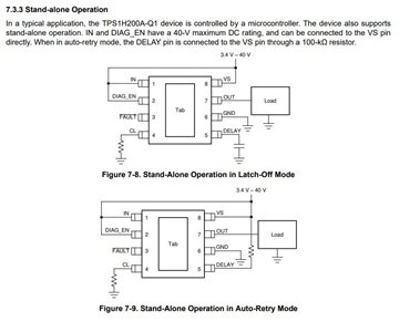
1. I found there is conducting current through DELAY pin when IN/DIAG_EN are off and VS/DELAY pull-up are ON, why should DELAY pin have through current ?

2. CAN I change DELAY pin pull-up resistor ?  or it must be 100k even pull-up power supply is different ? how does it work

  • Hi Nia,

    A strong pull-up is considered one of relatively less resistance that allows current to flow through; a weak pull-up is considered one of relatively high resistance that makes it harder for current to flow through. How much voltage is being supplied to the VS node? The absolute maximum voltage the delay pin can handle is 7V. 

    Thanks,

    Rishika Patel 

  • Hi, Rishika~

    VS node is connected to battery, about 10-16V 

    The reason we care about through current of DELAY is it directly connect to battery, and increase leakage current about 0.05mA,why so big current?

    I'm really curious about this DELAY pin, its maximum voltage is 7V but reference current diagram connect it up to 40V, how does it work ?

  • Hi Nia,

    There is a voltage divider configured on the delay pin so that is why it will not see 10-16V. You are trying to operate in the auto-retry mode so, the delay pin has to be pulled high. 

    To confirm, the resistor highlighted in yellow is 100kΩ and the one in blue is 1005Ω, right?

    Thanks,

    Rishika Patel 

  • Hi,Rishika~

    sorry about the misunderstanding. the yellow one is 100kΩ, but the blue one isn't 1005Ω, actually the blue one is 0Ω,and it isn't  Mounted in this case,just for debugging.

    Does DELAY pin have internal pull-down resistor ?

  • Hi Nia,

    The delay pin has an internal pull-up resistor. The voltage on the delay pin should not exceed the absolute maximum rating of 7V. If the blue resistor is not populated, then it is basically open. The goal is to externally pull the delay pin high, correct?

    Thanks,

    Rishika Patel 

  • Hi, Tishika~

    The yellow resistor (100k) is populated,so it's pulled up. 100k pull-up to 10-16V.

    "The delay pin has an internal pull-up resistor" -this is why through current happen in delay pin when this HSW disable & pull-up power still there, right ?

    Question about the absolute maxmum rating of 7V, quote datasheet as below picture : in this reference case, the delay pin is connected to  VS(this is what i did too) through a 100k resistor, it still could work cause internal pull-up,right?   I'm wondering how to choose this pull-up resistor if pull-up voltage changes.

    Is it ok that change 100k to 82k ?

  • Hi Nia,

    Yes, so the delay pin can be pulled up to VS if it is less than the maximum rating. For example, if delay was pulled up to VS = 5V with the way you configured it, the pin could handle it but if it is larger than the 7V, we cannot guarantee proper functionality, and the pin may get damaged. If you have a separate, smaller constant voltage source, you can pull the delay pin up to that (not necessarily just VS). A resistor divider like the one in your schematic would work too (populate the blue resistor) but for small VS voltages, the voltage on the delay pin could be really small depending on the resistors you select. Also, technically yes, since the delay pin has an internal pull up, it does not need additional external circuitry except for reinforcement. 

    Thanks,

    Rishika Patel