This thread has been locked.

If you have a related question, please click the "Ask a related question" button in the top right corner. The newly created question will be automatically linked to this question.

BQ25750EVM: Power path issues

Part Number: BQ25750EVM
Other Parts Discussed in Thread: BQ25750

Tool/software:

Hi,

We are facing below issues with EVM board related to power path and state of charging.

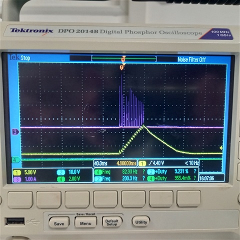
  1. System is in Active/OFF MODE: when input voltage is applied on VAC (for the moment we use a 24Vdc power supply), the charger fails to start and reboots continuously. Our expectation is to charge the battery when VAC is available.
  2. System is in CHARGING MODE: when input voltage is removed on VAC, the charger fails to toggle from VAC to VBAT and reboots continuously. Our expectation is to supply the system seamlessly from battery when VAC is not available.
  3. Our interested range of battery charging voltage i.e. VBAT is from 20 V to 30 V. And interested range of charging current is 50 mA to 3000 mA. Are Internal ADC enough accurate to be used for SOC determination (Battery current and Battery voltage monitoring)?

Please check and support.

Regards,

Saravana

  • Hello Saravana,

    Thanks for being patient with this. I'll get back to you tomorrow on this question.

    Best Regards,
    Ethan Galloway

  • Hello Saravana,

    We have an FAQ on the BQ25750 power path that may be helpful.

    1. I have a few questions to help us debug this:

    • Do you have a system load applied during this time?
    • What's the BQ25750EVM's charging current? - If the charging current is too high, the BQ25750EVM may brown out the input supply when it starts to charge.

    2. I have a few similar questions:

    • What's the system load here?
    • Can you remove C7 and C39 from the EVM? The reduced capacitance will reduce the inrush current through the BATFETs.
    • Can you use auto reverse mode here instead?

    3. The BQ25750's ADCs are not accurate enough to determine the state of charge.

    Let me know if you have any questions about this.

    By the way, we also have a general BQ2575X Family FAQ as well.

    Best Regards,
    Ethan Galloway

  • Hi Ethan,

    Please find below response for your questions.

    1a.  Do you have a system load applied during this time?

    • Yes we have a system load (approximately 100mA)

    1b. What's the BQ25750EVM's charging current? - If the charging current is too high, the BQ25750EVM may brown out the input supply when it starts to charge.

    • The charging current is set at 1.1Amp maximum by HW. Even with CE pin low or high to activate or deactivate the charge, the charger fails to start.
    • Additional observation: The issue seems to be at BATFET control level which does ON/OFF/ON/OFF in a loop. We planned to power microcontroller when VAC is applied. If uC see a toggle signal on BATFET, a solution is to Force BATFET to turn off via the FORCE_BATFET_OFF register bit and put back to ON.

    2a. What's the system load here?

    • We have a system load at approximately 100mA.

    2b. Can you remove C7 and C39 from the EVM? The reduced capacitance will reduce the inrush current through the BATFETs.

    • Even without C7 and C39, we have the issue. But we will remove these capacitors to reduce peak current.

    2c. Can you use auto reverse mode here instead?

    • We test the auto reverse mode by activate auto reverse mode when VAC is present. When VAC is removed, we wait 2sec and then deactivate reverse mode. This solution seems working.

    3. The BQ25750's ADCs are not accurate enough to determine the state of charge.

    • We will then use external current and voltage monitors connected to ADC input of uC (I2C bus also possible). Can we use the existing RBAT_SNS to connect external current and voltage monitors? Request you to provide design recommendation along with reference schematic, parts, constraints etc.

    We have additional question with respect to below observation:

    Condition: System is OFF and nothing is connected on the BQ25750EVM (no VAC/no VBAT). When we connect the Battery on VBAT, the charger fails to start and reboots continuously. 

    Above capture shows SYSTEM voltage (yellow) and SYSTEM current (purple) when the issue appears.

    It seems that adding a 10 nF capacitor between BATSRC and BATDRV fixes the problem. We would like to understand the technical rationale behind this. If capacitor is necessary, any recommendation on the value to choose? Do we have to add resistor in serie also? 

    Please check and support.

    Regards,

    Saravana

  • Hello Saravana,

    Thanks for the new information.

    Can we use the existing RBAT_SNS to connect external current and voltage monitors? Request you to provide design recommendation along with reference schematic, parts, constraints etc.

    This should be fine to use external ADCs to monitor the voltage and current to determine the battery SOC. Can you use a battery fuel gauge to calculate the SOC? This may be an easier solution.

    It seems that adding a 10 nF capacitor between BATSRC and BATDRV fixes the problem. We would like to understand the technical rationale behind this. If capacitor is necessary, any recommendation on the value to choose? Do we have to add resistor in serie also? 

    What's your battery voltage here? If you connect a DC voltage to VBAT, does it show the same behavior?

    We recommend a 10nF capacitor to slow down the BATFET turn-ON and turn-OFF time when the battery is above 30V. This protects the charger from damage from battery hot-plugs.

    If you are going to use auto-reverse mode, you can remove the BATFETs. When the BATFETs are removed, connect BATSRC to SRP and leave BATDRV floating.

    Best Regards,
    Ethan Galloway