This thread has been locked.

If you have a related question, please click the "Ask a related question" button in the top right corner. The newly created question will be automatically linked to this question.

BQ76952: How can I test using a DC power supply?

Part Number: BQ76952

Tool/software:

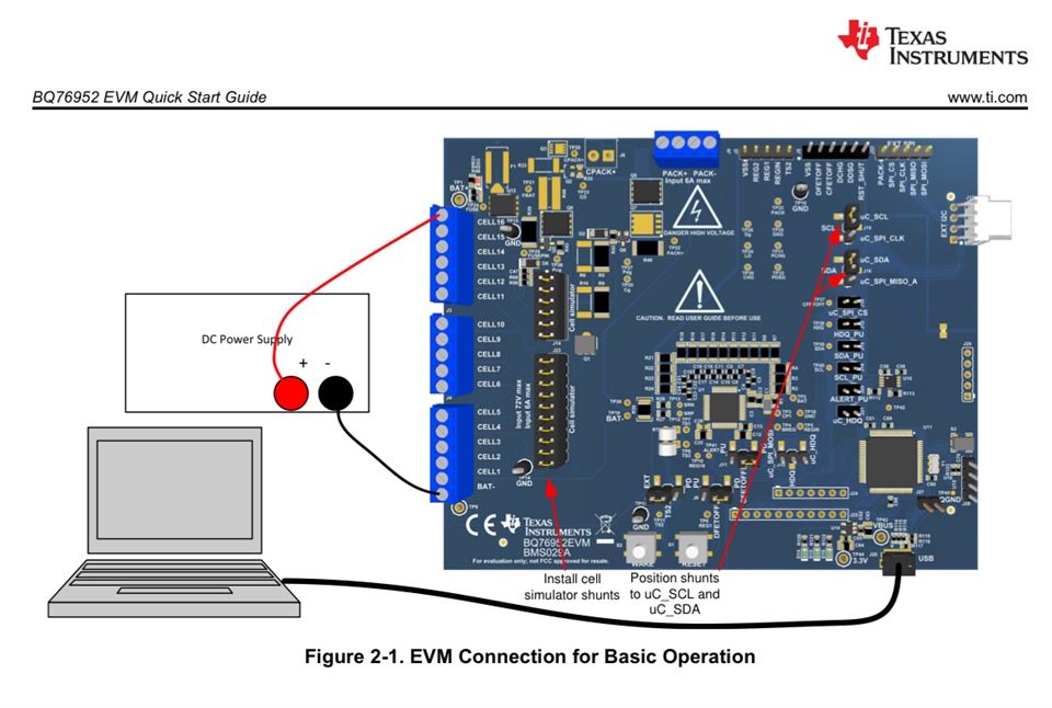
I read the EVM user manual which says that I can test the module by connecting the DC supply between bat- and V16, however, I do not have the EVM module. Can I still do this without the EVM and how can I achieve a way to test 6s with a DC power supply. 

  • Hello Miguel,

    t I can test the module by connecting the DC supply between bat- and V16, however, I do not have the EVM module. Can I still do this without the EVM

    I am a little confused from this statement. Are you asking if you can test the module without the EVM module? Or are you asking if you can test the BQ76952 without the EVM module? If it’s the latter, yes, you can test the BQ76952 without an EVM module and on your own custom board. 

    how can I achieve a way to test 6s with a DC power supply. 

    To use only 6S, please follow this Cell Connections FAQ and Table 16-3. Terminating Unused Pins from the datasheet.

    Best Regards,
    Alexis

  • Hi Alexis!! Im sorry for the confusion I am not the best with explaining things. I wanted to know how I can test the IC without batteries and only using a DC power supply. I saw that on the EVM module the dc power supply was connected to Bat+ and VSS which makes sense, I just wanted to know if I could do the same with the IC itself. If there are no batteries connected to the IC and I am using the DC supply to simulate the overall BAT+ and BAT- power, how would I connect this? I am sure its a lot easier than I am thinking however I want to make sure I dont damage the chip, thank you!

  • Hello Miguel,

    Thank you for clarifying. You can just use a power supply without actual batteries to test the EVM. However, if you are not planning on using the EVM itself, and want to test with a power supply, you would want resistors in place to 'simulate' the number of batteries you want expect your system to have. Please refer to Figure 5-10. Schematic Diagram Pin Configuration from the EVM User Guide and refer to the 'Cell Simulator' on the right side. 

    Best Regards,
    Alexis

  • Hey Alexis I am a little confused, I tried this but now what’s happening is that when I supply a voltage under 3v my CHG pin is low and anything above 3.7V my CHG pin outputs voltage relative to my input voltage. I am thinking this is due to not having any code running and the IC being stand alone but I am not sure. Any thoughts?

  • Hello Miguel,

    Most likely, the device entered SHUTDOWN mode as the top-of-stack voltage fell below the Power:Shutdown:Shutdown Stack Voltage. More information about this can be found in Section 7.5 SHUTDOWN Mode of the technical reference manual.

    When the CHG FET driver turns of, the CHG pin discharges toward the BAT pin level. This is discussed further in Section 16.5 FET Driver Turn-Off of the datasheet. 

    To confirm this, do you mind checking the REG18 voltage and the TS2 pin voltage?

    Best Regards,
    Alexis

  • Hmm ok that makes some sense. MY REG18 is producing 1.8V and my TS2 pin is not giving any voltage. I have TS2 going to a 10k ohm resistor tied to ground. I am getting a proper CP1 voltage and my system with a resistor ladder is pulling about .015A. 

  • Hello Miguel,

    TS2 should be left floating if the device is intended to enter SHUTDOWN mode. If your part was entering SHUTDOWN mode and the TS2 pin was held LOW, the part will enter soft SHUTDOWN state. REG18 should be 0V if it entered SHUTDOWN mode. 

    More information can be found in the following FAQs:
    1. Soft Shutdown FAQ
    2. Shutdown FAQ

    Best Regards,
    Alexis

  • So I fixed my resistor ladder and am now seeing 3.7, 7.4, and 11.1 for my 3s system at the resistors. Reg18 is 1.8V and TS2 is left floating right now. CHG is still high and am not sure why. I am very confused. Maybe I missed something in the TRM but what mode would the IC be in if only the CHG fet is on, reg is on, and TS2 is left floating?

  • Hello Miguel,

    Section 7 Operational Modes from the TRM can help you determine which modes your device is in. 

    Best Regards,
    Alexis