This thread has been locked.

If you have a related question, please click the "Ask a related question" button in the top right corner. The newly created question will be automatically linked to this question.

BQ25798: BQ25798

Part Number: BQ25798

Tool/software:

HI Jeff,
As said in in the earlier contest regarding shipFET to need to connected to complete cut of power from battery when powered off the system.

We added the external shipFET, with gate driven by SDRV, between the battery and BAT pin. still we see the voltage from the battery output.


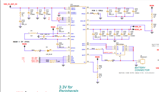
We have also given bellow resistors to be set when powered off.

[  104.180783] bq25790-charger 0-006b: Device is shutting down...
[  104.186632] bq25790-charger 0-006b: Executing shutdown / poweroff sequence...
[  104.194060] bq25790-charger 0-006b: R14:CHRG_CTRL_5 register set to ShipFET 0x98 successfully
[  104.202861] bq25790-charger 0-006b: R2E:ADC_CTRL register set to 0x30 successfully
[  104.210726] bq25790-charger 0-006b: R2F:FN_DISABLE_0 register set to 0xFE successfully
[  104.218925] bq25790-charger 0-006b: R30:FN_DISABLE_1 register set to 0xF0 successfully
[  104.227116] bq25790-charger 0-006b: R18: register set to 0xd5 successfully
[  104.234265] bq25790-charger 0-006b: R11:CHRG_CTRL_2 register set to 0x42 successfully
[  104.262723] reboot: Power down

Can you please tell what we are missing to achive complte shutdown off battery when powered off?

  • Hi Mj,

    Has input power been removed?  Shipmode or shutdown mode require no voltage on VACx.  If so, where do you see the battery voltage, on SYS pin?  I see on your schematic a diode from VDD_5V?  Is there an external 5V applied?

    Regards,

    Jeff

  • Hi Jeff,
    External power supply is completely removed, there is no where supply given to system.

    I see voltage  on SYS pin. 

  • Hi Mj,

    Is there a voltage on the charger's SDRV pin? 

    Regards,

    Jeff

  • Commnd	I2CSlv	Addr	Data	Comment (All Values in Hex)
    w	D6	00	04	#REG00
    w	D6	01	01	#REG01
    w	D6	03	00	#REG03
    w	D6	05	2C	#REG05
    w	D6	06	00	#REG06
    w	D6	08	F2	#REG08
    w	D6	09	05	#REG09
    w	D6	0A	23	#REG0A
    w	D6	0B	00	#REG0B
    w	D6	0D	4B	#REG0D
    w	D6	0E	3D	#REG0E
    w	D6	0F	22	#REG0F
    w	D6	10	80	#REG10
    w	D6	11	45	#REG11
    w	D6	12	00	#REG12
    w	D6	13	00	#REG13
    w	D6	14	98	#REG14
    w	D6	15	AA	#REG15
    w	D6	16	C0	#REG16
    w	D6	17	7A	#REG17
    w	D6	18	54	#REG18
    w	D6	19	00	#REG19
    w	D6	1B	00	#REG1B
    w	D6	1C	00	#REG1C
    w	D6	1D	01	#REG1D
    w	D6	1E	00	#REG1E
    w	D6	1F	00	#REG1F
    w	D6	20	00	#REG20
    w	D6	21	00	#REG21
    w	D6	22	00	#REG22
    w	D6	23	00	#REG23
    w	D6	24	00	#REG24
    w	D6	25	00	#REG25
    w	D6	26	00	#REG26
    w	D6	27	00	#REG27
    w	D6	28	00	#REG28
    w	D6	29	00	#REG29
    w	D6	2A	00	#REG2A
    w	D6	2B	00	#REG2B
    w	D6	2C	00	#REG2C
    w	D6	2D	00	#REG2D
    w	D6	2E	B0	#REG2E
    w	D6	2F	FE	#REG2F
    w	D6	30	F0	#REG30
    w	D6	31	05	#REG31
    w	D6	33	03	#REG33
    w	D6	35	12	#REG35
    w	D6	37	12	#REG37
    w	D6	39	12	#REG37
    w	D6	3B	10	#REG3B
    w	D6	3D	10	#REG3D
    w	D6	3F	03	#REG3F
    w	D6	41	00	#REG41
    w	D6	43	00	#REG43
    w	D6	45	00	#REG45
    w	D6	47	00	#REG47
    w	D6	48	19	#REG48

    Hi Jeff,
    Yes voltage is there at SDRV pin.

    Even i tried to set manually with reg 14 to 98 still the board is in ON condition.
    What am i missing ?
    Is circuit connection correct with respective to shipFET?


    I see on your schematic a diode from VDD_5V? (Jeff) ? . NO it is just an arrow mark.


    No size specified (using byte-data access)
    0 1 2 3 4 5 6 7 8 9 a b c d e f 0123456789abcdef
    00: 04 01 a4 00 32 2c 01 40 f2 05 23 00 dc 4b 3d a2 ???.2,?@??#.?K=?
    10: 80 45 00 01 98 aa c0 7a 54 00 32 00 00 01 00 00 ?@.????zT.2..?..
    20: 00 00 00 00 00 00 00 00 00 00 00 00 00 00 b0 fe ..............??
    30: f0 04 3d 01 ea 14 10 13 00 13 00 0e fb 0f 6e 03 ??=?????.?.???n?
    40: 5d 00 49 00 0f 00 00 00 19 ff ff ff ff ff ff ff ].I.?...?.......
    50: ff ff ff ff ff ff ff ff ff ff ff ff ff ff ff ff ................
    60: ff ff ff ff ff ff ff ff ff ff ff ff ff ff ff ff ................
    70: ff ff ff ff ff ff ff ff ff ff ff ff ff ff ff ff ................
    80: ff ff ff ff ff ff ff ff ff ff ff ff ff ff ff ff ................
    90: ff ff ff ff ff ff ff ff ff ff ff ff ff ff ff ff ................
    a0: ff ff ff ff ff ff ff ff ff ff ff ff ff ff ff ff ................
    b0: ff ff ff ff ff ff ff ff ff ff ff ff ff ff ff ff ................
    c0: ff ff ff ff ff ff ff ff ff ff ff ff ff ff ff ff ................
    d0: ff ff ff ff ff ff ff ff ff ff ff ff ff ff ff ff ................
    e0: ff ff ff ff ff ff ff ff ff ff ff ff ff ff ff ff ................
    f0: ff ff ff ff ff ff ff ff ff ff ff ff ff ff ff ff ................
    root@imx8mp-lpddr4-evk:~#  

  • Hi Mj,

    The schematic looks correct.  The registers are correct as well. With REG0x14[7]=1 and VBUS<UVLO=3.4V, SDRV turns off. 

    Regards,

    Jeff 

  • HI Jeff,
    How do i read the battery voltage when running on battery , here is an issue when running only on battery there is a drop in voltage.

    when power supply given in charging mode. the voltage 3.854
    root@imx8mp-lpddr4-evk:~# i2cget -y -f 0 0x6B 0x3b
    0x0f
    root@imx8mp-lpddr4-evk:~# i2cget -y -f 0 0x6B 0x3c
    0x0e

    when power supply removed discharging mode. the voltage suddenly drops to 3.413 (as soon as we removed)
    root@imx8mp-lpddr4-evk:~# i2cget -y -f 0 0x6B 0x3b
    0x0d
    root@imx8mp-lpddr4-evk:~# i2cget -y -f 0 0x6B 0x3c
    0x55
    root@imx8mp-lpddr4-evk:~# 

    Even when measured from multi meter the reading are same, how do we take stable reading, when power disconnected.? 
    Is there any register to be set ?

  • HI MJ,

    There is resistance from the charger IC BATP sense point and the cells in the battery pack.  When charge current is flowing across this resistance, the BATP measures ICHG*Resistance+Vbatcells.

    Regards,

    Jeff

  • Hi Jeff,

    So, how do we achieve the actual voltage of the battery when power supply not connected?

  • Hi MJ,

    That is the actual voltage of the battery, i.e. when no current is flowing into or out of the battery, there is no resistive drop so the ADC measurement is the voltage of the battery pack cells.

    regards,

    Jeff

  • Hi Jeff,

    But when I remove the battery from the system and measured from multimeter, then there will be 0.4V difference (I mean higher).

    when compared with connected system.

  • Hi MJ,

    The system is pulling battery discharge current so that Idischarge*Resistance is creating a 0.4V drop.

    Regards,

    Jeff