This thread has been locked.

If you have a related question, please click the "Ask a related question" button in the top right corner. The newly created question will be automatically linked to this question.

TPSF12C1: How to avoid AEF output saturation

Guru 12115 points
Part Number: TPSF12C1

Tool/software:

Hi,

We have been adjusting the peripheral components of the TPS12F1 but have not been able to achieve the expected performance. We would appreciate your support on the following inquiries:

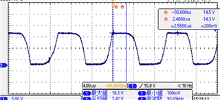
  1. We understand that if the input noise level is too high, the AEF output may saturate. If the INJ pin voltage waveform appears as a square wave, does this indicate that the AEF output is in saturation?

  2. If the INJ waveform is sinusoidal, can we assume that the AEF is not in saturation? Also, when considering a square wave as a saturated waveform, increasing the capacitance between Line-FG has changed the waveform from a square wave to a sinusoidal wave. However, the current capacitance value is significantly large, making it impractical for mass production. Are there any other methods to suppress saturation besides increasing the Line-FG capacitance?

  3. Using PSPICE for TI, we simulated a frequency close to the PFC operating frequency (80kHz). The simulation results showed a square wave at the INJ pin, similar to actual operation. Furthermore, in the simulation, when the oscillation frequency is set below 100kHz, the INJ output waveform consistently appears as a square wave. Could you explain the reason behind this phenomenon?

  4. The datasheet states that "to avoid amplification of low-frequency noise, the VDD ripple voltage should be kept within ±20mV." Currently, we are supplying power through an LDO from a DC power source, but due to switching noise, the ripple exceeds 20mV until it stabilizes. Is it mandatory to keep the ripple voltage within ±20mV?

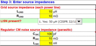
  5. The "Regulator CM noise source impedance (Csrc, Rsrc, Lsrc)" in the Quick Start Tool appears to refer to the impedance of the AC/DC power supply stage after the filter. Could you provide guidelines on the typical values for these parameters?

We appreciate your time and support. Looking forward to your response.

Best regards,

Conor

  • hello conor,

    I will get back to you on this

    thanks and regards

  • Hi Naresh,

    We look forward to your response.

    Thanks,

    Conor

  • Hi Conor,

    thanks for your patience,

    1. Yes, if the INJ output is like a square wave, in most cases, it means that it is saturating. Please check the peak-to-peak INJ voltage swing. If the swing is closer to VDD, then it is saturating. 

    2. There are several other ways to suppress saturation. For example, you can increase the regulator side Y-capacitors from the current value that you are using. You can also reduce the gain of the AEF loop to improve saturation. You can do this by increasing RG resistor. 

    3. The device is designed to support switching frequencies above ~80kHz and above. if the switching frequency is lower, we expect more chances of saturation. But the above-mentioned suggestions should help in reducing the saturation. If you need more information on how to reduce the effect of saturation, please refer to the following link and read through it - [FAQ] TPSF12C1 and TPSF12C3 power-supply filter IC FAQs - Power management forum - Power management - TI E2E support forums

    4. Yes, it is highly recommended to keep voltage ripple within 20mV. 

    5. The values mentioned in the quick start are the typical values for grid source impedance and regulator source impedance.  

    I would recommend to first start with the quick start calculator. enter the parameters in step1, step2 and step3 and tune the parameters in step 4, 5 and 6 so that you get a INJ pin voltage in step 7 that is not saturating, and you have to ensure that you have a stable loop gain and phase. After ensuring it is stable and not saturating in quick start calculator, then go ahead with measurements

    Thanks and regards,