This thread has been locked.

If you have a related question, please click the "Ask a related question" button in the top right corner. The newly created question will be automatically linked to this question.

UCC29002: Issues with using the UC29002 with a COTS boost converter

Part Number: UCC29002

Tool/software:

Hi TI Experts,

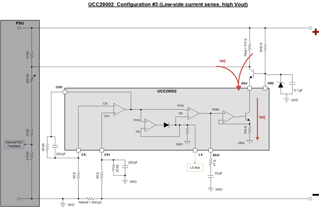
I'm designing a circuit to share the load equally among 4 boost converter outputs. Each boost converter is rated for 1500W and the output voltage is adjusted by the internal Rsense pot of the boost converter to 60V. I used the latest UC29002 Design Calculator to choose the values for the load share circuit (see the attached file). I chose Configuration 3 with low-side current sensing, keeping in consideration the high output voltage of the boost converter.

For Radj, I had to choose a value greater than 299 Ohms, so I set it to 510 ohms.

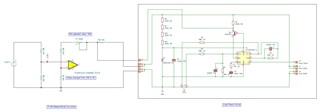
When I connect the load share circuit to the boost converter, with just a single converter, the output voltage drops from 60V to the value of the input voltage (24V). On investigating the boost converter circuit, I found that the connection of Radj to the boost converter causes it to come in parallel with the Rsense pot and this causes the feedback voltage to the boost converter circuit to increase. The attached file shows the simplified internal circuit of the feedback portion of the boost converter and its connection to the load share circuit. The Rsense pot is set to around 200K.

If I were to increase Radj beyond the value of the Rsense pot (to say 1Meg), I could keep the feedback voltage within range. However, this causes the compensation cap Ceao to increase to almost 3.8MF.

Let me know your thoughts on a possible solution.

Regards,

Mohan.

Boost-Converter+Load-Share.pdf

UCC29002_Design_Calculator_V1.1_17-9-24 - for 1500W boost converter.pdf

  • Hello Mohan,

    Can you please share the original UCC29002 design calculator Excel instead of the pdf? This will help with debugging.

    The purpose of the Radj is to sink the Iadj current. See the diagram below from Uli Goerke. 

    UCC29002 Sharing Blocks2.pdf

    Best,

    Jonathan Wong

  • Hello Jonathan,

    Thanks for your reply. I've uploaded the Excel with the changes I had made.

    The datasheet on page 19 describes the issue I'm facing. "In cases where the RSENSE value is relatively high, the maximum ADJ current IADJ(max) may increase the module's VOUT too much. In such cases, an external adjustment resistor RADJ is connected between the ADJ pin and the VOUT rail after RSHUNT. This arrangement places RADJ effectively in parallel with RSENSE and an artificial SENSE+ voltage is created by the voltage drop across RADJ∥RSHUNT due to the current sunk by the internal NPN transistor at the ADJ pin. RADJ scales the portion of IADJ that can flow through RSENSE to limit the maximum amount of voltage adjustment ΔVADJ(max) allowable for the module." 

    Even when IADJ = 0, RADJ (510 Ohms) comes in parallel with RSENSE (200K) and increases the feedback voltage to the error amplifier. I will see if changing the RSENSE value can provide the fix.

    Regards,

    Mohan. 

    UCC29002_Design_Calculator_V1.1_17-9-24 - for 1500W boost converter.xlsx

  • Hello Mohan,

    Thank you for sharing your calculator. We will look into your calculator and get back to you.

    Regards,

    Jonathan Wong

  • Hello Jonathan,

    Since the RADJUST of 510 Ohms coming in parallel with the RSENSE pot was the cause of the problem, I modified the boot converter by soldering a 10K resistor in series with the pot. Effectively, the 10K resistor became the new RSENSE. Then, I could adjust the pot to give 60V at the output of the boost converter.

    When the voltage at the Load Share pin was increased (as a simulation of higher current in a parallel module), the voltage at the EAO pin increased followed by an increase in the output voltage of the boost converter. I presume that this is the expected behaviour of the UCC29002.

    I will follow this up with building and testing 4 parallel modules.

    Let me know your thoughts on this change that I made.

    Regards,

    Mohan.

  • Hello Mohan,

    I made a schematic that integrates your block diagram with the internal block diagram of the UCC29002. Let me know if there are mistakes. Looking at the block diagram, I do not see any issues with the setup.

    Regards,

    Jonathan Wong

  • Hello Jonathan,

    The circuit representation looks correct. The circuit for load sharing has now been designed and sent for fabrication (I added a small resistor-divider circuit to simulate the load without necessarily passing 25A current). I'll post my observations after completing my tests.

    Thanks for your help.

    Regards,

    Mohan. 

  • Hello Mohan,

    Thanks for the update. Let us know if you continue seeing issues.

    Regards,

    Jonathan Wong