A related question is a question created from another question. When the related question is created, it will be automatically linked to the original question.
If you have a related question, please click the "Ask a related question" button in the top right corner. The newly created question will be automatically linked to this question.
The simplest method for reverse polarity is using keyed hardware connectors to ensure it is physically impossible to connect in reverse.
If current is only flowing in one direction, i.e. input to a charger IC that will not used in reverse/OTG mode, a FET can be used as explained at https://www.ti.com/lit/an/slva139/slva139.pdf.
If current is flowing in both directions, e.g. a battery getting charged then discharged, protection circuits get more complicated. Unfortunately, we do not have a good circuit based solution for this.
My issue is I am using the part for an automotive application. So no keyed connector there. The idea is to have an iot car tracker that controls remotely the vehicle and has a battery backup. The UPS feature in conjunction with the Li-ion controller was perfect for my application, in which the IC automatically boosts the battery when the supply is not available. It can also measure and change two input supplies, which is useful. I think my best solution is two diodes, one for each supply in series.
I think I can manage lossy using a good Schottky diode. My circuit won't consume more than 15W, around 1.3A at 12V, so not many losses at the diode. The other option would be to combine something like the TPS552892 with a simple lithium controller and some comparators to automatically switch the input to battery backup when disconnected. I am not really sure what would be the best option.
Can you have a series diode to VAC input? From what I understand, VAC inputs are the only ones that would not be protected in case of a Reverse polarity event. A small voltage drop in VAC shouldn't interfere in normal operation, and some functionality can be compensated via software.
Is my reasoning correct, or am I missing something?
VACx is high impedance voltage sense pin. I haven't tried it (and can't easily test on the EVM) but I see no reason why their couldn't be a Schottky diode in series.
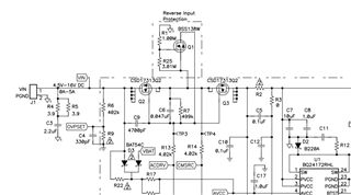
The Zener/TVS diode should block the negative voltage back feeding to ACDRV pin, but I am worried that the capacitor between Gate and Source might provide a path for the negative voltage during a transient event and damage the input with the short negative pulse.
That is a concern. I found a reverse polarity protection circuit for input voltage for an older device in https://www.ti.com/lit/ug/sluu462a/sluu462a.pdf. It doesn't protect the VACx lines however.
With reverse input, I think Q1 turns on, shorting Q2 and Q3 gate to sources (and IC CMSRC to ACDRV). Any reverse current flows through this FET and Q1 diode. This circuit may not work with BQ25798 because it does not have the CMSRC pin and has the VACx pins instead.