Tool/software:
Hello,
I've a TPS61094 that's used for the main energy manager of a board. In this case, Vin comes from USB (typically 5V) or (exclusive) a solar panel, and the Vout is set to 4.8V. It's set in all automatic mode (EN = MODE = 1) with automatic switch to Vcap when Vin disappear.
The circuit works fine both when Vin is present (correct output, no ripple, the second stage outputs 3.3V for the microcontroller) and not (still get 4.8V on output as expected). However, when Vin isn't present, the power drawn from the main capacitor is 100x higher than expected.
In order to diagnose the issue, I've powered the 2nd stage (4.8V) with a Power profiler Kit II, set Vin at 0V and shorted the Vcap. I've put the microcontroller to sleep and got a measured current of 62µA as expected (which gives a power consumption of 297µW)
However, with the hack removed, and a fully charged capacitor (2.1V, as measured by the microcontroller), I'm getting a current consumption of 7mA or 25mW, which is 100 times higher than expected.
I've checked all the SUP net for any potential current consumer:
1. This net is connected to an input pin of the ADC of the microcontroller, which is isolated when sleeping, with a (datasheet declared) 50nA of leakage current. Isolation means that both high and low transistor are opened. While the microcontroller is sleeping, there is still 3.3V on its VCC pin (checked), so I don't think it's back powering the microcontroller from its GPIO.
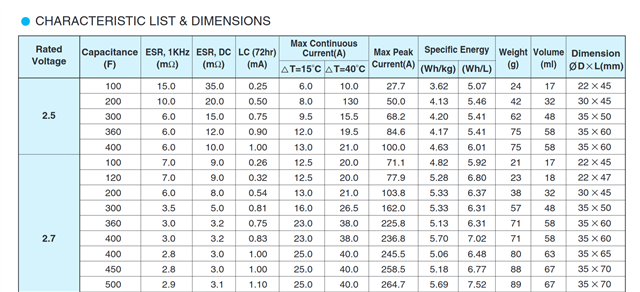
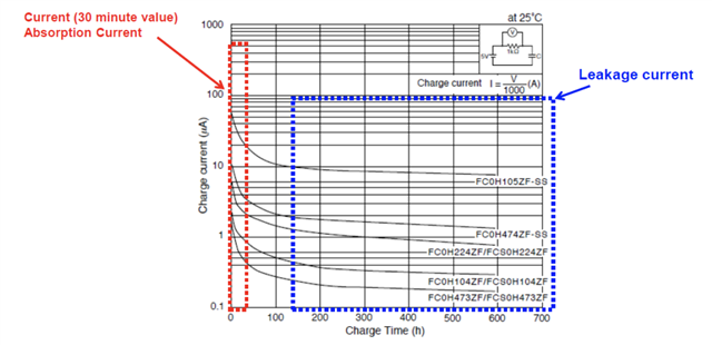
2. The supercapacitor used is a GreenCap EDLC DB (2.7V 500F) which is supposed to have an ESR of 3.1mOhm and a leakage current of 1.1mA
3. The C10 is a ceramic capacitor MLCC in 0402. It's supposed to have an insulation resistance > 10GOhm
4. The Vcap to EN/MODE pins via the BAT54C Schottky diode should only leak 5µA = 2* ((2.1V - 0.1V) / 800kOhm)
So I don't explain the large current consumption I'm seeing.
Also, the method used to measure the power consumption of the supercap is the following:
1. The voltage of the supercap is measured by the microcontroller via its ADC pin (validated as correct to within +- 8mV) with a digital multimeter in parallel to the supercapacitor
2. When the microcontroller enters sleep for a duration d0, the voltage is sampled as Vi
3. Upon waking up, the voltage is sampled again as Vm.
4. The microcontroller then enters sleep again for a duration d1
5. Upon waking up, the voltage is sampled as Vf.
I have modeled the energy consumption in 2 phases, the "entering sleep" phase and the "sleeping" phase. Thus, the energy consumed by the microcontroller for the first period (d0) is
E0 = Ee + Ps * d0 (respectively: E1 = Ee + Ps * d1 for the second period)
with Ee the "entering sleep" energy and Ps the power consumed during sleep.
I'm then computing Ps as Ps = (E1 - E0) / (d1 - d0)
The energy is computed from basic physic formula: E = 1/C * V², so the E0 is computed as E0 = 1/2 * C * (Vi - Vm)²
The capacitance used here is the true calibrated capacitance, not the nominal capacitance (via measuring its voltages after a fixed period with constant current charging), and it's already smaller (280F instead of the official 500F) than the "official" value.
Can you explain why I'm seeing this huge consumption for this circuit, and how to fix it to get the expected value ?
Thank by advance.
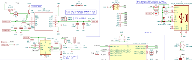
Schematic:
Characteristics of the supercap: