This thread has been locked.

If you have a related question, please click the "Ask a related question" button in the top right corner. The newly created question will be automatically linked to this question.

TPS7A7200: Simulation Model - Soft Start implementation?

Part Number: TPS7A7200

Tool/software:

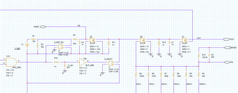
I noted that for the models available on the product page that the Soft Start feature does not appear to be implemented.  This is stated in the encrypted model example for PSPice for TI, and demonstrated in LTSPICE for the unencrypted model by varying the SS capacitance from OPEN to 1uF, which is the stated full range in the data sheet.  Inspection of the model file shows the following - and only line related to the SS pin:

R_TPS7A7200_R_NR_SS         SS 0  1G  

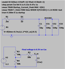
I am attempting to reduce the output current during startup to an acceptable limit based on the capacitance and other elements in my circuit. However, I cannot determine what the relationship is for Imax during the startup condition.

Was this intentional, and if so, can the model be updated to include the function?  I need to show that my SS implementation has an acceptable margin against the IC max Iout, and is able to satisfy the requirements of other circuit elements of the voltage ramp rate.

  • Hi Steven,

    Unfortunately, the TPS7A7200 macromodel uses an older model architecture that prevents us easily modifying it to add the soft start functionality. It may be possible to build a rough model of the TPS7A7200's startup behavior that would allow you to evaluate inrush current, though such a model may not accurately model other characteristics like PSRR, noise, and transient response. 

    Best Regards,

    Alex Davis

  • Alex.

    Thanks for the response here.

    I think that is OK.  It would allow me to evaluate some of the parameters independently, right now focusing on startup. I do have a separate model which uses the full SPICE implementation for evaluation. I am using LTSpice v24.0.12 (latest as of this date). I am using the circuit below, and I am leery about its accuracy since the results are highly dependent on a few factors - namely timestep and integration method.  Trapezoid techniques appear to be too conservative, and gear method seems to approach the correct theoretical peak value when I remove the ideal diode, but still not as accurate as I would have hoped.  I have taken some inspiration from the second method in the following article:

    power supply - Different ways to implement soft start in SPICE modeling? - Electrical Engineering Stack Exchange

    Since the soft start current limit during startup for the TPS7A7200 is not published, I don't believe I can implement what is described.  However, the method I did choose to start with uses a voltage dependent voltage source.  That source output is gated by the startup timeout for the part (700ns), and then I set the Vout proportional to the voltage on Css. The capacitors have some ESR and ESL to help demonstrate peak current. From the IC datasheet figures, this seems to be a reasonable approach to guide the Vout rise.  However, I am not confident that the current limit is being set appropriately.  From the SPICE model, it appears that the output resistance may be primarily set by the 2 1mohm resistors on the output pin.  Other than that, I don't have any insight into FET impedance or gain during that time. For clarification, the P1V2DC is independent of the 1.2V source representing the internal reference to the part for startup.

    From Figure 6.2, this approach seems appropriate.  If not, I would greatly appreciate a recommendation.

    Thank you.

  • Hi Steven,

    My apologies for the very delayed response. This method should be reasonably accurate, but won't account for external feedforward capacitance if it's present in your design. The device current limit should remain consistent throughout its operation, though the current limit circuit typically takes a small amount of time (10s to 100s of µs, typically) to activate. 

    If a soft-start circuit is present on the reference, and feedforward capacitance is used, one option is to approximate the LDO as a transconductance amplifier. That simplification does tend to overestimate the bandwidth of the amplifier, but if large Css/Cff are used, they will be the dominant factors in the startup behavior of the device. 

    I put together a startup-only model for the TPS7A7200 which corresponds decently with the datasheet startup waveforms at various Css values. 

    Model

    I've tested this in a couple different SPICE tools, and it runs well. I can't validate it in LTSpice, unfortunately, but I suspect it'll work there as well.

    Here's the basic architecture:

    The bulk of the netlist implements UVLO and EN thresholds and hysteresis (not shown in the image above). When both thresholds are met, a pulldown switch on the reference turns off, allowing the soft start cap to start charging. A delayed copy of this enable signal and another switch (S_DELAY) gates the soft-start reference signal from reaching the error amplifier (G8) to better match the datasheet behavior. The error amplifier consists of two stages above, the first implements a fairly arbitrary voltage gain (G8 + R19) with a high frequency rolloff for stability from capacitor C1. This voltage is capped at ~5V to keep the model better bounded. 

    The resulting voltage controls another transconductance stage, G1, which approximates the output device. This is limited to source between 0 and 3.1A to model the current limit and source-only behavior of the LDO. Resistors and a small, approximated feedforward capacitor to implement the any-out circuitry complete the amplifier stage. 

    I've parameterized a few characteristics of the model attached, if you want to try out parameter variations from the datasheet. 

    Best Regards,

    Alex Davis