This thread has been locked.

If you have a related question, please click the "Ask a related question" button in the top right corner. The newly created question will be automatically linked to this question.

TUSB546-DCI: Display issue

Part Number: TUSB546-DCI
Other Parts Discussed in Thread: TPS65987DDK

Tool/software:

Hello,

We are facing display issue when we use combination between TPS65987DDK and TUSB546.
I'm asking same question to TPS65987DDK support team, however, I would like to confirm this from viewpoint of highspeed signal.

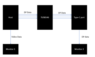
We configure custom board as DFP only with alternate only mode(DisplayPort). (This means we do not use USB3.x)
We could get HPD signal from TPS65987DDK after CC negtiation and input this signal to TUSB546 correctly.
However, we are facing following issue.

 * We observed that we can NOT confirm display when we use Type C to Type C cable with customer board.

Here is detail.
We did test with several pattern. We could not confirm display case of type-c to type-c cable with customer board image source.
To check whether this issue is related to cable quality, we did test by using PC as image source. However, when we used PC as image source, we could confirm display on any case of display.
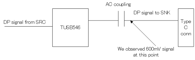
We confirmed HPD is asserted and also confirmed DP signal at near of type-C connector (checked signal after passing through AC coupling (approx +/-600mV) in all following cases.


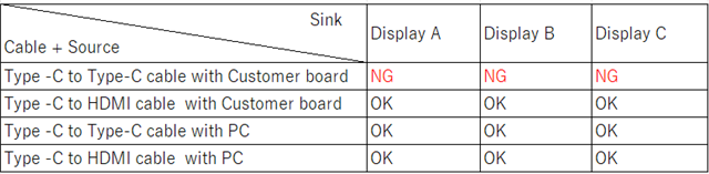
The first question is below.

Q. Is  +/-600mV which I described above expected signal level ?

Best Regards,

  • Hi,

    Yes 600mV is about expected. Have you tried both orientation of the USB-C cable?

    Can you perform a continuity test to make sure the TUSB546 internal mux is set properly?

  • Hi,
    >Have you tried both orientation of the USB-C cable?
    Yes, we did both cable insertion.

    >Can you perform a continuity test to make sure the TUSB546 internal mux is set properly?
    We confirmed signal at following point. And we could see display in case of type-C to DP cable. So internal path is set correctly.
    Could you please tell me how we perform "continuity test" except above ?


    Best Regards,


  • Hi,

    Are you able to have multiple displays connected to this host?

    If you are. Then you can do the following tests to wee where the hang-up is. 

    1) connect monitor 1 to host ideally HDMI to DP

    2) connect monitor 2 to host

    3) on monitor 1 see if monitor 2 is detected in display settings

    4) see if you can read information abut the monitor such as resolution an refresh rate in advances display settings

  • I believe that the issue is most likely due to improper routing of the DP signal when both sides of the signal is type-C. 

    Just to double check you have tried both normal and flip orientation at the monitor connectors and the TUSB546 connector correct?

  • Hello,

    >Just to double check you have tried both normal and flip orientation at the monitor connectors and the TUSB546 connector correct?
    For above, I'm not sure difference between following previous question.

    >Have you tried both orientation of the USB-C cable?
    For above, as I said perviously, I did check both cable insertion.

    Best Regards,

  • Hi,

    The normal and flip orientation applies to both ends of the type-C cable.

    I only asked about the side connected to the USB-C connected to the TUSB546, I didn't ask about the type-C cable connected to the monitor. My follow-up question was regarding the type-C cable connection with the monitor. 

    Did you try the debug steps I listed out?

  • Hi,

    >Did you try the debug steps I listed out?
    Let me confirm what you imagine.

    Do you assume "Host" is PC ?
    If possible, could you show the configuration image ?

    Best Regards,


  • Hi,

    The setup I imagine is something like this:

    Is this possible with your system? Does your system have more than 1 video out port?

  • Testing would be completed on monitor 2 and monitor 1 would be a reference

  • Hi,

    Make sense !
    Here is our configuration.


    We have two different display out. However, we could NOT output these two at the same time.

    Best Regards,

  • Hi,

    Looks like we will not be able to use the setup I proposed. Are you able to connect the outputs of the type-C port to a scope using a compliance setup?

    Looks similar to this:

    My theory is that with HDMI across type C there is no lane swap meaning links[0-3] out will connect to links[0-3] in respectively. 

    However for DP across type-C the cable connections are not as straightforward: Are you able to try all 4 scenarios and see if one works?

    Another way to look at the system would be as follows. Can you confirm that the DP lanes are correctly routed to the type-c pins?


    Can you share a schematic of your system?

  • Hello,

    Thank you for your reply.

    >Are you able to connect the outputs of the type-C port to a scope using a compliance setup?
    It is difficult to realize this setup at this time.

    >Are you able to try all 4 scenarios and see if one works?
    I'm not sure which setting sink side is applied, however from viewpoint of source side, eventually I connect "DP0P DP0N signal to "A10" and "A11 of type C connector.

    Do these four case mean I use same cable but change insertion pattern ?

    >Can you confirm that the DP lanes are correctly routed to the type-c pins?
    Yes, we confirmed waveform after AC coupling both figure 8-8 and figure 8-9 case depending on cable orientation and this was expected route.

    >Can you share a schematic of your system?
    I sent schematic related to this part on private message.

    Best Regards,

  • Do these four case mean I use same cable but change insertion pattern ?

    Yes, try normal and flip orientations at the connecter for the DP alt mode source and the connector at the DP alt mode sink. 


    >Can you confirm that the DP lanes are correctly routed to the type-c pins?
    Yes, we confirmed waveform after AC coupling both figure 8-8 and figure 8-9 case depending on cable orientation and this was expected route.

    Are you able to measure the waveforms on the other side of the type-C cable?

    What is the length of the type-C cable/ was the type-C to HDMI cable much longer or shorter?

    Can you try multiple type-C cables?

    This could possibly be an EQ issue. are you to quantify the pre-channel (path before redriver) and post-channel (path after redriver) loss in dB? 

  • Hello,
    >Are you able to measure the waveforms on the other side of the type-C cable?
    It is difficult because other side is commercially available monitor.

    >What is the length of the type-C cable/ was the type-C to HDMI cable much longer or shorter?
    We did not measure exact length, but cable is less than 2m.

    >Can you try multiple type-C cables?
    Yes, We tested by using three different type C cable.

    >This could possibly be an EQ issue. are you to quantify the pre-channel (path before redriver) and post-channel (path after redriver) loss in dB? 
    We did SI simulation by using IBIS-AMI. And we use proper setting which simulation suggest.

    Best Regards,

  • Hi,

    Can you measure the common mode voltage of the AUX bus? Can you capture the AUX log?

    This will allow me to understand where the signal is getting stuck. 

    Have you tried a different monitor?

    What is the status of the control pins for the TUSB546?

    Are you able to achieve USB3 communication without any alt mode?

  • Hi,

    Sorry for my late reply.

    >Can you measure the common mode voltage of the AUX bus? 
    I measured two case.
    One is "displayed" and another one is "No displayed".

    Case of displayed : 
    SBU1/SBU2 : 0.52V / 2.65V
    Case of No displayed
    SBU1/SBU2 : 0.27V / 2.84V

    It seems that "case of displayed" is out of recommended spec of datasheet, but worked fine.

    >Can you capture the AUX log?
    Today, I can borrow PD analyzer with AUX.
    I will check it and share result.

    >Have you tried a different monitor?
    Yes, I have tried totally 4 different display.

    >What is the status of the control pins for the TUSB546?
    Do you mean CTLx and FLIP ?

    >Are you able to achieve USB3 communication without any alt mode?
    No. Our board do not route USB3 line.

    I have one question.

    * We use display port signal with 1 lane.
    However, it seems that there is no setting for 1 lane in TUSB546.
    Therefore, I use "4lane DP" setting. Is it availale to use "4lane DP" setting with only 1 lane DP signal case ?

    Best Regards, 

  • Hi,

    Yes using 4 lane DP and only having one lane connected should be fine. 

    Yes what is the status of CTLx and FLIP? and does it change when the cable orientation is changed?

    One is "displayed" and another one is "No displayed".

    Do you use a different source for the displayed case? what's the difference between the two?

  • Hi,

    >Yes what is the status of CTLx and FLIP? and does it change when the cable orientation is changed?
    Yes, I confirmed behavior of CTLx and FLIP pins are what I expect. And when I change insertion direction, status of FLIP pin was also changed.

    >Do you use a different source for the displayed case? 
    Yes, source is different in this case.
    (Monitor is same.)

    >what's the difference between the two?
    I used PC as source in "Displayed" case. And I used color pattern of our custom board as soruce in "No Displayed" case.

    >>Can you capture the AUX log?
    >Today, I can borrow PD analyzer with AUX.
    >I will check it and share result.
    I got AUX log by using PD analyzer(ellisys's analyzer).
    I included 4 pattern.(Please see attached zip file)

    1. Source is PC and connect to our(TED) monitor.
    2. Source is PC and connect to customer's monitor.
    3. Source is our custom board and connect to our(TED) monitor.
    4. Source is our custom board and connect to customer's monitor.
    (Above "1" and "2" are case of "Displayed". And above "3" and "4" are case of "No displayed".)

    It seems that we can see communication all case, but the contents of the log of "No displayed" case appear to be less than "Displayed" case.
    Is there any idea which point we should check ?

    Best Regards,
    EllisysAnalyzer_20250502.zip

  • HI,

    What I'm looking for in these files is where in the DP link training comes to a halt. Based on that information we will be able to isolate the issue further. 

    I am unable to open the CTRT files.

    What software are you using for the aux log? Are you able to share in a different format/ send me the link to the software used?

  • What what I have seen between this thread the the PD team thread:https://e2e.ti.com/support/power-management-group/power-management/f/power-management-forum/1497385/tps65987ddk-hpd-assertion-issue

    It looks like aux is communicating properly as well. This issue likely is that link training is failing. 

  • Hi,

    Thank you for your reply.

    >What software are you using for the aux log? Are you able to share in a different format/ send me the link to the software used?
    I use "Ellisys Type-C analyzer tracker"
    Ellisys - Type-C Tracker - Type-C, PD, DP, TB, and more

    As you mentioned, I believe your USB PD support team have above application.

    >It looks like aux is communicating properly as well. This issue likely is that link training is failing. 
    Could you please tell me why you conclude "link training is failing" ?
    If possible, could you please tell me what cause become main reason in general ?

    Best Regards,
     

  • Hi,

    As I suspected this is not an internally approved software. I have contacted IT for approval to install, but this may take a day or two. In the mean while, try adjusting the EQ settings of the device. 

    The connecting sequence is typically as follows:

    1) HPD connection detected and display EDID read

    2) begin link training

    3) send clock pattern to sink and wait for clock lock

    4) if no lock increase the swing and repeat step 3.

    5) if no lock increase the pre-shoot and repeat step 3.

    6) clock locks and send data patterns

    7) increase swing until lock

    8) increase pre-shoot until lock.

    9) after clock and data lock begin sending video data.

    The issue is most likely a signal integrity issue where the sink is unable to lock on the clock/ data coming in. Are you able to measure eye diagrams at your lab? I would like to see an eye diagram of the data coming out of the USB-C connector. Additionally, if this is not possible we may need to brute force and try every possible EQ combo to see what works. 

    IBIS AMI data provides a general range for what the EQ should be set to. Use the data gathered by this as a gauge, but most likely this loss of the system will be worse tan what IBIS AMI predicts. 

    I recommend starting at the highest EQ value and stepping down.

  • Hello,

    >IBIS AMI data provides a general range for what the EQ should be set to. Use the data gathered by this as a gauge, but most likely this loss of the >system will be worse tan what IBIS AMI predicts. 
    We did simulation by using IBIS AMI.
    We set 6.5dB according to simulation result. And also we tested to set 4.9dB, 7.5dB, 8.6dB. However we still observe issue.

    When you can install tool, I would like you to confirm. However, according to AUX log, it seems that link training (CR and channel EQ) was performed properly.
    (Finally, I could confirm "CR done" and "EQ done" on the log.)


    Best Regards,

  • Hi,

    It seems that the link training happens ok as well. I notice that the source data seems to be eDP which is supported by our part, but ASSR scrambling is typically not supported by monitors. Is there a way you can disable ASSR on the incoming data/ enable the monitor to decode ASSR?

  • Hello,

    Thank you for your support.
    I could confirm display on monitor with type-C cable by disabling ASSR.
    I will close this thread, and I really appreciate for your dedicated support.

    Best Regards,