This thread has been locked.

If you have a related question, please click the "Ask a related question" button in the top right corner. The newly created question will be automatically linked to this question.

TPS26750: Issues configuring port as DRP

Part Number: TPS26750
Other Parts Discussed in Thread: TPS25751, BQ25756, , BQ25756EVM

Tool/software:

Hello everyone,

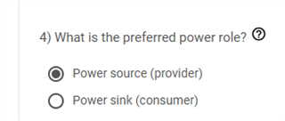
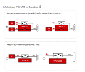
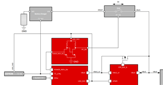
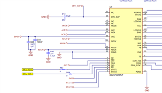
We are working with the TPS26750, trying to configure it as a Dual Role Power (DRP) device capable of delivering up to 240W. In most of our test cases, it seems to behave as expected, but we are seeing some strange behavior in specific scenarios.

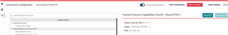
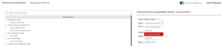
The CC lines appear to advertise correctly, as shown in the attached figure. When we connect a regular USB-C wall charger to the port, the PPHV line ramps to 5V, which is the expected behavior.


However, the issue arises when we connect a smartphone to the port. The phone initially displays a charging notification, but then immediately stops charging and repeats this cycle as if it is rapidly connecting and disconnecting. I've attached a scope capture of the PPHV line while the phone is connected.

We're currently unsure if this is a configuration issue, a setup/hardware problem, or something else entirely.

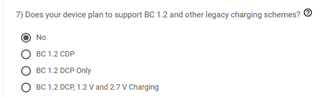
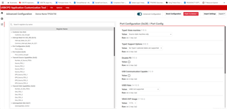
The TPS26750 is supposedly configured via an EEPROM connected to the I2C port, and we've extracted the configuration using the TI GUI. We're attaching those configuration files to this post as well for reference.


Any help or insight would be greatly appreciated.

Thanks in advance!

  • Hello,

    I do not see the configuration files.  Please try to attach and/or share over the messaging application.

    Do you have a means to capture the PD communication (CC lines)?

    Does the phone require BC1.2 support and are the appropriate fields selected?

    Can you confirm the Preferred power role?

    Regards,

    Chris

  • Thank you for your answer, Chris

    The forum chat is not allowing me to attach files other than images If you could supply me an email address I will share the configuration files with you happily.

    What is the maximum power that can be sourced/consumed? 240W
    Preferred Power Role? Power Source
    Supported USB Highest speed? No USB Data
    BC1.2 Support? No

    We don't believe that is related to cellphone configuration, we already tried that with many cellphones and all work the same way. Apart from that we have used this cellphone on TPS25751 Development modules and managed to charge the cellphone without any issues not using BC1.2. 
    We are also using TPS together with the BQ25756 for battery charging. The battery charger configuration is as follows.
    Battery charger component: BQ25756
    Percentage above the negotiated PD Contract for setting INDPM: 0%
    Percentage Below the negotiated PD Contract for setting VINDPM on the battery charger: 10%
    Battery charging voltage: 1.536V
    Battery charging current 5A
    Charge termination current: 2A
    Pre-charge current: 2A

    Unfortunately, we do not have a PD analyzer for the CC lines. We could develop FW to access the I2Ct to read configuration directly from the TPS, do you have any sample code for this? 

    Best regards
    Francisco

  • I already tried all those methods but looks like .json files are not supported to be attached in this messages

  • Hello,

    Can you configure the device as a source only to determine if the issue is related to the DRP negotiation?

    Regards,
    Chris

  • Hello,

    /cfs-file/__key/communityserver-discussions-components-files/196/testConfig.json

    Sorry that the attach file is not working.  Can you view the attached json file?

    Regards,

    Chris

  • Yes, we can try changing the profile but it will take some time as we dont have any FW yet for doing it. Do you have any other recommendation to test in the meantime?

    What could happend if there is no battery connected to the system if using the BQ25756 configuration? Im also not sure on how the power paths is configured when power to be drain from the PD Controller is lower than 15W. Would the system drive power from the PP5V power path or if PPHV is configured only PPHV will be used for draining or supplying power?

    And your configuration looks good, the only difference with ours is sink power, you configured it as 100W we have it configured to 240W

    Thank you for your help Chris

  • Hello,

    And your configuration looks good, the only difference with ours is sink power, you configured it as 100W we have it configured to 240W

    In the attached json file I have changed the role to source only and did not bother to change the sink PDOs.  

    What could happend if there is no battery connected to the system if using the BQ25756 configuration? Im also not sure on how the power paths is configured when power to be drain from the PD Controller is lower than 15W. Would the system drive power from the PP5V power path or if PPHV is configured only PPHV will be used for draining or supplying power?

    The TPS26750 will attempt to write to the BQ part via I2Cc.  If the voltage is not provided then the PD will fault (most likely under voltage fault on VBUS).

    Im also not sure on how the power paths is configured when power to be drain from the PD Controller is lower than 15W. Would the system drive power from the PP5V power path or if PPHV is configured only PPHV will be used for draining or supplying power?

    The TPS26750 does not have a PPHV.  The power path, PP3, is the external power path.

    Do you have any other recommendation to test in the meantime?

    Can you measure the CC lines to see what is happening upon connection?

    For your reference:

    https://www.ti.com/tool/PMP41115

    https://www.ti.com/lit/ug/tidt407/tidt407.pdf#page=2

    Regards,

    Chris

  • Hi Chris sorry for the delay here I wanted to run some tests before anwering

    • The TPS26750 will attempt to write to the BQ part via I2Cc.  If the voltage is not provided then the PD will fault (most likely under voltage fault on VBUS).

    Looks like this was the main issue, we connected a 3s battery to the system and we were able to charge a cellphone from the battery and we stopped seeing that erratic behaviour.


    • The TPS26750 does not have a PPHV.  The power path, PP3, is the external power path.

    It calls my attention that in the advanced configuration only source PDO1 has the possibility of chosing the power path, is it not possible to configure other PDOs to use PP1?

    We are having one more issue now that is that our battery looks like it is not beeing charged. After connecting a battery charger to the USB C port PP3 gets activated correctly and we see 5V at PPEXT.


    Then PG flag at the BQ25756 goes low meaning that we have a correct input at the charger but the STAT1 and STAT2 flags are both low meaning that charging is disabled. 
    We have the CE input at the BQ25756 tied to 3V3 with a pull-up resistor, that means that in order to enable charging the TPS would need to set DIS_CE_PIN  to 1 and set also to 1 EN_CHG bit in the BQ 
    Is there anyway to know if the TPS is doing this? Or can we manage to make the TPS to do this from the I2Ct interface? If not, the only solituion to this would be to place a pull down in the CE pin?

    Thank you!

  • Hello,

    It calls my attention that in the advanced configuration only source PDO1 has the possibility of chosing the power path, is it not possible to configure other PDOs to use PP1?

    The default value is PP3.  The ability to select PP1 is available but I will need to make an inquiry if that is a mistake in making that option available in the GUI tool.  We do not allow the configuration of the power path based upon the PDO, the intent is to only support the external power path.

    I can double confirm with the GUI team to understand exactly which writes are being made to the BQ from the PD, however, in the reference design the CE pin is pulled low.

    https://www.ti.com/lit/df/tidmdd3/tidmdd3.pdf#page=4

    Regards,

    Chris

  • Hello,

    I was able to confirm that the PD does not set the DIS_CE_PIN in the I2C writes to the BQ.  The EN_CHG is controlled in the I2C writes to the BQ.

    Regards,
    Chris

  • When I configure the TPS26750EVM with BQ25756EVM in bidirectional SINK and SOURCE mode, with both input and output power at 100W (using a 240W cable), and the BQ side is connected to a 36V battery load, I encounter the following issues:

    • When set to sink priority, it charges the battery normally, but it cannot switch to source mode to charge a mobile phone.

    • When set to source priority, it can charge the mobile phone normally, but it cannot switch to sink mode to charge the battery.

    • After confirming that the HV_SYS voltage is stable, the PPHV voltage is unstable, and the PP_EN LED keeps flashing.

    I would like to ask, what settings in the USBCPD_Application_Customization_Tool need to be adjusted to make DRP work properly?

  • Hello,

    I would like to ask, what settings in the USBCPD_Application_Customization_Tool need to be adjusted to make DRP work properly?

    I do not believe there is a setting in the tool.  Once the port partners have established roles (source and sink) there needs to be some logic to determine when to swap roles.  The embedded controller would send a message to the PD to issue the request to do a power role swap.  Please see the different 4CC messages to swap roles:

    https://www.ti.com/lit/ug/slvucr8a/slvucr8a.pdf#page=59

    Regards,

    Chris

  • Hello,

    I apologize for not explaining clearly earlier.

    The issue I'm facing is not related to dynamic role swapping, but rather with the USB Type-C connector being unplugged and replugged.

    For example, I use a Type-C charger to charge the battery. Once the battery is fully charged, I unplug the Type-C charger and then connect a mobile phone to the same port. However, in this case, the system fails to switch to Source mode to supply power to the phone.

    This is the issue I'm currently encountering. Thank you.

  • Hi Hardy, 

    When set to sink priority, it charges the battery normally, but it cannot switch to source mode to charge a mobile phone.

    When the PD controller is set to prefer sink (i.e. Initiate Swap to Sink [5] = 1 in register 0x29), it will automatically initiate and send a power role swap request to the phone to become the sink. 

    When set to source priority, it can charge the mobile phone normally, but it cannot switch to sink mode to charge the battery.

    Similarly, when the PD controller is set to prefer source (i.e. Initiate Swap to Source [7] = 1 in register 0x29), it will automatically initiate and send a power role swap request to the phone to become the source. 

    You could disable the preference to one role by setting both Initiate Swap to Sink [5] and Initiate Swap to Source [7]  to 0 but keep Process Swap to Sink [4] and Process Swap to Source [6] set to 1. These settings will allow the PD controller to swap power roles when prompted by the port partner. If the phone is set to prefer being a sink, then it will issue a power role swap with your device. I highly suggest using a PD analyzer to capture the CC communication between both port partners. This will help identify which power role the phone is preferring. 

    Please let me know if you have additional questions/concerns. 

    Best Regards, 

    Aya Khedr

  • Hi Aya Khedr,

    Thank you for your suggestion. After making the adjustments, both my SINK and SOURCE functions are working properly. Would you recommend keeping Initiate Swap to Sink [5] and Initiate Swap to Source [7] set to 0 at all times? Thank you.

  • Hi Hardy, 

    I am glad to hear that it is working as expected. 

    Would you recommend keeping Initiate Swap to Sink [5] and Initiate Swap to Source [7] set to 0 at all times?

    Keeping these bits disabled allows the port partner to prompt your device when it desires a power role swap and should be reliable in most cases. 

    If there are specific cases where your device needs to swap power roles, the embedded controller would send a message to the PD to issue the request to do a power role swap.  Please see the different 4CC messages to swap roles here: 

    https://www.ti.com/lit/ug/slvucr8a/slvucr8a.pdf#page=59

    Best Regards, 

    Aya Khedr