This thread has been locked.

If you have a related question, please click the "Ask a related question" button in the top right corner. The newly created question will be automatically linked to this question.

BQ25750: Input/output capacitors location

Part Number: BQ25750
Other Parts Discussed in Thread: BQ24610, BQ25756

Tool/software:

Hi team,

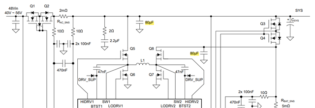
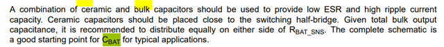
When designing BQ25750, there is a question: the location of the input and output capacitors. There is no clear requirement in the specification. The following screenshot:

However, in actual use, the current detection before and after Rsen represents the average (input/output) current, or the inductor current.
Compared with BQ24610, Rsen is required to be placed after the capacitor for cycle-by-cycle detection, enter the dcm mode, and reduce power consumption.

My questions are:
1. Does BQ25750 have no requirements for the location of the input and output capacitors?
2. Will BQ25750 maintain BCM mode under PFM? Then is it through SW zero-crossing voltage detection or sen resistor zero-crossing current detection

BRs,

Rannie

  • Hello Rannie,

    1. Yes, there are requirements for the placement of the capacitors. We have an FAQ post for more information.

    2. The BQ25750 operates in discontinuous conduction while in input voltage DCM. PFM is disabled in input voltage DCM.

    Let me know if this answers your questions.

    Best Regards,
    Ethan Galloway

  • Hi Ethan,

    1.  According to the FAQ, it mentioned that the 80uf input capacitor should be 40uf+40uf on both sides of Rac. The output capacitor is the same. Right? But in the datasheet 80uF caps are both placed close to the MOS side.

    Datasheet:

    FAQ:


    2. How does the device BQ25750 recognize light load? In addition, in DCM mode, is the synchronous MOS forced to be turned off, or is the synchronous MOS turned off when the reverse current of the synchronous MOS is detected cycle by cycle?

    BRs,

    Rannie

  • Hello Rannie,

    Thanks for working with this.

    1. The datasheet picture is just a simplification of the circuit and is not an exact drawing. Please balance the capacitors across the sense resistors.
    2. The synchronous MOS is allowed to operate in DCM mode. The BQ25750 detects the current through the inductor and decides DCM or PWM mode. The exact current for the transition from DCM to PWM depends on the inductance, VIN, VOUT, and VOUT. Generally any current greater 1.5A causes the BQ25750 to be in PWM mode.

    Let me know if you have any questions about this.

    Best Regards,
    Ethan Galloway

  • Hi Ethan,

    Thanks for your reply. Can you help to check when the synchronous MOS be turn off in one cycle if working at DCM? according to monitor the reverse current on MOSFET?

    BRs,

    Rannie

  • Hello Rannie,

    I don't quite understand your question. The BQ25756 measures the current by looking at the current sense resistor and the SW1/SW2 pins. The BQ25756 doesn't use the switching FETs to measure the current.

    Best Regards,
    Ethan Galloway

  • Hi Ethan,

    Thanks for your reply.

    The design uses a 12V power input to charge a 21V battery. The data sheet includes only the adapter 12V power supply or only the battery power supply. There is no description of power switching and switching time parameters.

    So there are few questions for the following conditions:

    1. No VAC, only the battery exists and the voltage is normal. Connect VAC, when VAC meets the set operating window, how do ACDRV and BATDRV switch? Is there a dead time? Can the system maintain uninterrupted 150w power supply?
      If the battery voltage is higher than VAC. After connecting VAC, how the system power supply switches from battery to VAC. Will it wait for the voltage on the system side to drop to VAC before switching to avoid input reverse current?
    2. When both battery and VAC are present, if VAC is removed and switched to battery power supply. How to ensure that the 150w load on the system side is uninterrupted while reducing the surge impact caused by the voltage difference between VAC and BAT?
    3. Is BQ25750 suitable for uninterrupted switching on the system side? (Do not use automatic reversal mode. Automatic reversal will keep the charger working)

    BRs,

    Rannie

  • Hello Rannie,

    1. This is a very good question. We have an FAQ on the BQ25750 power path switchover that may help. The power path switchover normally takes a couple milliseconds to complete. I recommend using auto-reverse mode for higher power loads.

    2. Please read the power path switchover FAQ.

    3. What's uninterrupted switching? Are you referring to a uninterruptible power supply (UPS)? If so, can the customer use auto reverse mode to get VBAT≈VSYS and then disable reverse mode to activate the BATFETs? Would that work for the customer?

    Best Regards,
    Ethan Galloway

  • Hi Ethan,

    Thanks for your reply.

    The FAQ states that the FET has 8A overcurrent protection during switching. The customer's rated load current is around 15A. Does this mean it cannot be used?

    BRs,

    Rannie

  • Hello Rannie,

    Your welcome.

    The 8A current protection only applies while the FETs are in the process of switching over.

    Once the FETs are fully ON, the customer can supply a 15A load current.

    Let me know if this will work for the customer.

    Best Regards,
    Ethan Galloway

  • Hi Ethan,

    8A means the current will be limited at 8A but still works or will triggered the shutdown when exceeds 8A?

    BRs,

    Rannie

  • Hello Rannie,

    That's a good question. The BATFETs will turn-off once the current exceeds 8A. When the BATFETs turn-off from the current limit, the BATFETs will wait around 3ms and then proceed to try to turn-on again.

    Best Regards,
    Ethan Galloway