This thread has been locked.

If you have a related question, please click the "Ask a related question" button in the top right corner. The newly created question will be automatically linked to this question.

BQ25798: I am using TPS25751 USB-C PD controller with two BQ25798, SYS pin goes to TPS2121 to choose between BQ25798 sys pin and adapter.

Part Number: BQ25798
Other Parts Discussed in Thread: TPS55288, TPS25751, TPS2121

Tool/software:

I am using TPS25751 controller and two BQ25798 chargers along with TPS2121 (which Muxes the power) to deliver power to the system. Also, i incorporated TPS55288 to regulate the voltage.

Am I correct with the following?

1. From USB-C VBUS, it goes to the TPS25751 VBUS? 

2. from the same VBUS from USB-C, it shall go to TPS55288 as VIN and VOUT of the TPS55288 to the VBUS pin of BQ25798?

like this: USB C VBUS > TPS55288/TPS25751 VBUS > TPS55288 VIN > TPS55288 VOUT > BQ25798 VBUS? 

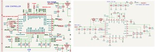
3. If i use two BQ25798 and a single TPS25751, how do i implement the USB data lines (D+ and D-) of BQ25798? Do I leave them floating or use them? or the TPS25751 does the job?

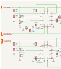
4. I am using two 2s1p battery packs and two BQ25798 to treat them separately, SYS pin of these two chargers will go to input pins of TPS2121 then added another TPS2121 to connect to the adapter. Can you comment if there will be no problem when the SYS pin served as IN1/2 in one of TPS2121 and another input from an adapter?

  • Hi Cid,

    I recommend reviewing the reference design with TPS25751 and BQ25798 at https://www.ti.com/tool/USB-PD-CHG-EVM-01.

    Regarding 1, yes.

    Regarding 2, I do not recommend connecting TPS55288 directly to the USB-C VBUS.  TPS55288 should connect to the output of the TPS25751.  USB-C port then TPS25751 then other IC is needed to get max output power from USB-C port.  I will forward to the TPS team for their confirmation and other ideas.

    Regarding 3, since both BQ25798 ICs have the same I2C addresses, are you expecting the TPS25751 firmware to configure both BQ25798 I2C register settings at the same time.  We have not tested that configuration.  If you are not using legacy USB BC1.2 adapters and only using USB-C, you can leave the BQ25798 D+/D- lines floating. 

    Regarding 4, I do not understand the purpose here.  Are you trying to triple diode OR SYS1, SYS2 and input adapter to the output?  If so, then wouldn't the output of the top TPS2121 need to be the input to the bottom TPS2121?  As long as the two BQ SYS pins are never tied together, the BQ25798s should function correctly.

    Regards,
    Jeff

  • Hi Cid, 

    As Jeff mentioned, the TPS55288 should be connected to the output of the PD controller which would be PPHV. What is the purpose of adding the DCDC in between the PD and BQ here? Typically PD PPHV is directly connected to the BQ input. 

    Best Regards, 

    Aya Khedr