This thread has been locked.

If you have a related question, please click the "Ask a related question" button in the top right corner. The newly created question will be automatically linked to this question.

TPS61376: Compensation network calculation question

Part Number: TPS61376
Other Parts Discussed in Thread: TPS61377

Tool/software:

Hello,

I've gotten somewhat confused on the compensation network calculations for the TPS61376. 
It seems following the datasheet example doesn't yield the component values that they've chosen.

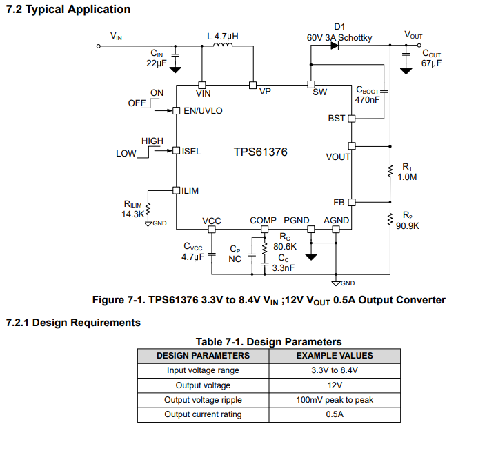
For example on figure 7-1 of the datasheet they have Cc as 3.3nF and Rc as 80.6k. 
The output resistance Ro = Vo/Io = 12V/0.5A = 24Ω

First thing I am unsure about regarding the calculation for Rc is the Kcomp value which they give as 6.5A/V . Is this a constant or does it depend on the inductor value chosen? I understand the peak current calcs for the inductance, but where does comp voltage come from?

Anyway skipping past this detail and going directly to the calculation for Cc which is given be equation 18 as Cc=(Ro*Co)/2*Rc

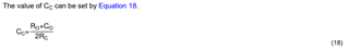
If we were to take the values of the components shown in figure 7-1 for Ro, Co and Rc we get
Cc = (24Ω*67uF)/(2*80.6kΩ) = 10nF
The calculation gives 10nF for Cc while the example image shows this as 3.3nf??
To get Cc as 3.3nF Rc would need to be closer to 200k!


Now where am I going with this?
I am asking this because I was hoping to use this part on a project where I have a 5V input and 12V output with an output current rating of 350mA, inductor 6.8uH and an output capacitance Co = 330uF. Problem is I have serious doubts about calculating the compensation network components since even the example seems inconsistent.

Hope someone could give me some assistance in the calculation of the compensation network.

Many thanks!

  • Hi Ruben,

    Datasheet only gives a preliminary approach about how to design proper loop compensation. Please share Cout part number and I'll calculate the compensation for you.

    Best Regards,

    Travis

  • Hello Travis,

    I can give you some details on the parts I plan to use:
    For Cout I am using an electrolytic capacitor from Panasonic, part number: EEEFK1E331AP.
    Additionally for the inductor I am using a 6.8uH inductor from Wurth Elektronik, part number 74438336068. Included this as I am not sure if it is a useful detail for calculating the compensation.

    I would be very interested to see how the process of the compensation calculations is done for this part, I am aware TI often provides a calculator tool for certain parts but unfortunately not for this one.

    Your assistance on this would be much appreciated!

    Best Regards,
    Ruben

  • An important detail I must add add; Since my original post I have reduced the output current from 350mA to 150mA. 

  • Hi Ruben,

    TPS61376 has the same internal loop circuit as TPS61377. I'll calculate the compensation and reply tomorrow. You can try TPS61377 excel calculation tool if you would like to see how the process of the compensation calculations is done for this part.

    Best Regards,

    Travis

  • Hello Travis,

    If you could help calculate those values for compensation that would be much appreciated.
    It is good to know the excel sheet for that other part is also possible.

    As a second question I plan to use this boost converter to step up the 5V from USB. From what I have read in the datasheet it recommends a 22uF capacitor at the input of the boost converter, however USB 2.0 standards advise no more than 10uF. Since the datasheet does not fully justify the need for a 22uF maybe I could use something closer to 8uF at the input? I am using a short cable <250mm. From what I've read on this other forum post here it seems the value of the input capacitance can be reduced significantly without causing a problem TPS61376: How to calculate the buffer capacitor value? - Power management forum - Power management - TI E2E support forums 

  • Hi Ruben,

    It depends on your parasitic inductance of your cable so I cannot tell exact value of Cin. You can test by probing Vin and see whether there's ringing on Vin waveform. As long as the Vin is steady, our IC will be okay.

    I've been too buzy today and I'll calculate the compesation tomorrow

    Best Regards,

    Travis

  • Hi Ruben,

    The 330uf Cout of your system is too large for your system and generated a ESR zero within cross frequency. I can adjust compensation parameter to eliminate this impact but this will sacrifice bandwidth. Please confirm whether you want to change Cout to smaller value like 47uf or you need to keep 330uf.

    Also, we recommend MLCC in parallel with electrolysis capacitor. Please also share part number of your MLCC.

    Best Regards,

    Travis

  • Hi Travis,

    Thank you for looking into this. I expect the load to remain constant for the most part other than the initial transient during start up.
    I plan on placing a 1uF MLCC capacitor in parallel with the electrolytic C0603C105K3RACTU from KEMET.
    The intention behind the large electrolytic was to help supply an initial inrush to the load, inspired by the application note High-Precision Input Average Current Limit Boost Converter, Facilitating More In.

    If the electrolytic capacitor causes significant harm by being 330uF I could consider reducing it down to 100uF or 47uF with an electrolytic such as EEEFKE101XAP or EEEFK1E470AV.

    Best regards,
    Ruben

  • Hi Ruben,

    Please ensure more than 10uF effective MLCC. The 330uF can be kept if you need to supply an inrush load. Change Cp to 220pf to eliminate the ESR zero. Rc and Cc value can stay at 80k, 3.3nf.

    Best Regards,

    Travis

  • Hi Travis,

    So to confirm, change the output MLCC capacitor to >=10uF, the 330uF electrolytic could remain.
    Keeping the original Rc and Cc and Rc=80.6k and Cc=3.3nF as shown by the image.
    So only the main change is adding the Cp = 220p. 
    Thanks you for helping out with this.

    Best regards,
    Ruben