This thread has been locked.

If you have a related question, please click the "Ask a related question" button in the top right corner. The newly created question will be automatically linked to this question.

LM5148-Q1: Request for Review and Schematic Confirmation

Part Number: LM5148-Q1
Other Parts Discussed in Thread: LM5148, LM5148-LM25148DESIGN-CALC, LM25148

Tool/software:

Hi,


I have designed a DC-DC converter based on the LM5148 IC family, with an input range of 40V to a nominal 48V, and an output of 24V up to 10A maximum.
For the design, I used TI’s Webench Power Designer and the LM5148-LM25148DESIGN-CALC tool.

I would like to kindly ask you to review the attached schematic if there is any problem with it.

Additionally, I have a question related to this design:

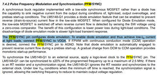
The 10A maximum load will not be continuous. Most of the time, the load current will be between 300mA to 1000mA, with occasional peaks up to 10A lasting a few minutes.
I have reviewed the LM5148 datasheet, and it appears that this variation in load current is acceptable without any issues. Could you please confirm this understanding?

Thank you very much for your support!
The schematic, Webench exported files, and design calculator sheet are attached.

Best regards,
ZM
VIN_to_24DC_Schematic .pdf2251.webench_Design.pdf5875.LM5148_LM25148_quickstart_calculator_A4.xlsm

  • Hi Abdurrahaman 

    Thanks for showing interest in our product!

    Engineer has been assigned to this thread. He'll get back to you on this

    Thank you

    Regards

    Onkar Bhakare

  • Hi Abdurrahaman,

    The schematic components are correct. I would like to draw your attention towards the following thing:

    - You have entered input capacitor values as 24.2 µF, but in actual due to derating the value would become 12.2 µF. This is not a problem since it will give input ripple less than 400 mV. You need not change the capacitor; this is just to draw your attention.

    Thanks,

    Pramanik Patel

  • Dear Pramanik and Onkar,

    Thank you for your prompt support and helpful feedback regarding my design!

    I appreciate your note about the input capacitor derating — it's good to know that even with the reduced capacitance, the input ripple will remain acceptable.

    Pramanik, I would like to kindly ask one more question:

    Considering that my application will mostly operate at light load (below 1000 mA) with only occasional peaks up to 10 A, could you please comment on the expected behavior of the LM5148 at light loads?

    Is there anything I should be aware of regarding stability, efficiency, or operation mode transitions at these lower current levels?

    Thank you again for your valuable support!

    Best regards,

    ZM

  • Hi,

    Since you have connected PFM/SYNC to VDDA it will work in PFM mode at light loads.

    It seems it will be in PFM at 1A load.

    For 1A the stability is not a concern.

    Thanks,

    Pramanik Patel