This thread has been locked.

If you have a related question, please click the "Ask a related question" button in the top right corner. The newly created question will be automatically linked to this question.

UCC256404: UCC256404

Part Number: UCC256404

Tool/software:

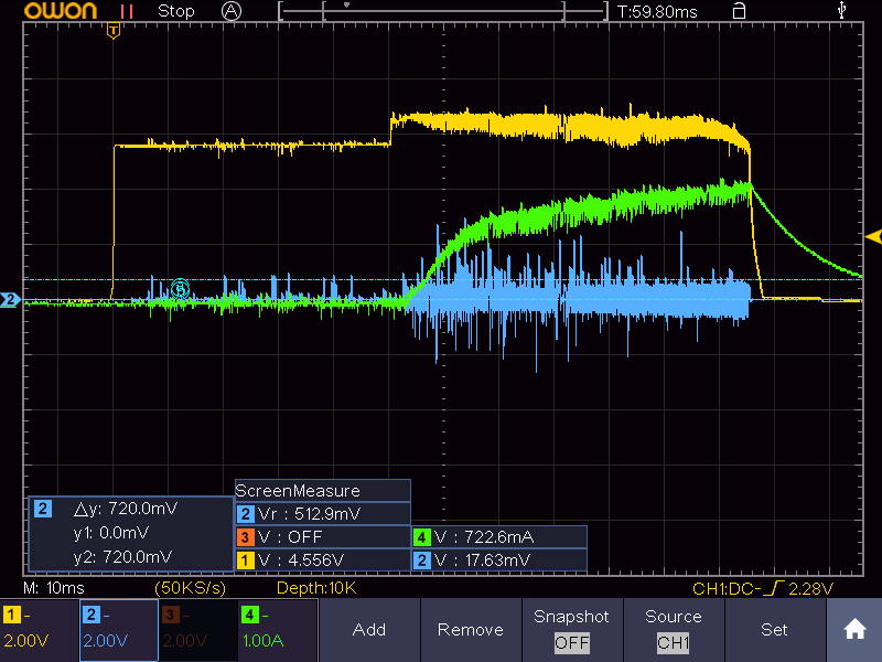
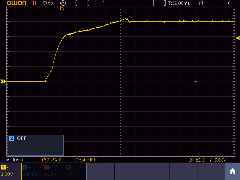
I found new problem with my design with UCC256404. When running device output is connected to load 80V / 4A, and load is disconnected, feedback primary (before optocoupler) is broken. There are destroyed zener diodes 24V, Zener diode 12V and 100R resistor between 80V and zener diodes 24V. Feedback is here feedback.pdf .

How to prevent to destroy feedback when load is fully disconnected?

  • When your load is removed, is the input removed too? Do you have any waveform? It is likely you have over voltage event on the Vout if your input is not disconnected, which damages the diodes. Please refer to the schematic examples in the EVM to design your feedback loop. 

  • I have no waveform. I had connected Load 80V / 4A, and load has been physically disconnected. Input has not been removed. After output disconnect, UCC256404 goes to error state and try every second to start. It not starts, and there was broken given zener diodes. Before the load disconnection, there was not any overvoltage in output.

  • You can fine tune the feedback loop to increase the bandwidth to avoid OVP. Please refer to the schematic examples in our reference designs. You can find many on ti.com.

    https://www.ti.com/reference-designs/index.html#search?keyword=ucc256404

  • I go througth lot of designs, and still have problem with feedback in testing. It works well with 80V/0.5-8A load, but system not starts with less load. Starting without load gets starting every 1 second restart. I try start with 1A load and decrease load. About with load 0.3A breaks  R297, D161 and D162 in attached feedback scheme. Vhen Output Voltage +80V is higher like 80V, D160 and D161 are quickly heating. I can increase  R297, but it decreases dynamic of feedback. Feedback is from this design: www.ti.com/.../tidrxp7.pdf 

    3073.feedback.pdf

  • First of all, the total breakdown voltage of 4 diodes is 78V. When you Vout is 80V, they will breakdown and consume power and heat up.

    Re-start every second means protection is triggered and controller attempts power up again every second. 

    Have you measured the bode plot of your feedback?

    Try to match your reference exactly and check again (add R621). Or you can design a type 2 filter (refer to EVM schematic)

    Feedback fine tuning is not an easy task but it is independent of which LLC controller you are using. 

  • No, I didn't measure bode plot of feedback. Can I find any info hot to do it? I'm very intersted of this.

    Today I measured (after increasing R297 from 100R to 200R) disconnection load (2A), and here is output voltage: No diodes breaks. But I think this is not solution. System cannot switch of output, when there is not load (in real there is 100k resistor in pcb connected to output). In my device will be minimum load 100mA). 

    Here is starting with R297 = 100R:

    and here is the same starting with R297 = 200R

    It looks the same. I'm interested too, how to decrease little overvoltage in starting.

  • Hi,

    Your attachments are not viewable so I cannot comment.

    There are many online resources teaching about how to measure bode plot. Google/Youtube/AI are your best friends here. Please also note that the system discussion is beyond the scope of the forum. 

    If you have a specific question on our ICs, please feel free to ask here.

  • Hello. I found measurement procedures with injector for create bode chart.

    I need help with these things too:

    1. I have problem to start with higher load. System is designed for 80V/10A but can start only with load 1,5A. After starting, it is not prolem to increase load it works well up to 7A, next system sometime switch off and restarts.

    With starting with the load higher as 2A it try start and every 1 second it restarts. Sometime it starts, sometime no. I measured all signals, problem is, I think, with ISNS setting. I used Cisns and Risns from device excel calculation. Cisns = 150pF, Risns = 90 Ohm. I try to decrease Risns too, time of starting with 2A load is longer, but not fully starts.OCP1 Ires is set to 27A, Isec to 66A. 

    Here is measuring of FB (yellow) ISNS (blue), Iout (green). How to set starting with max load ?

    2. How can I minimalize small overvoltage in starting. Now it is up to 8 V over 80V. I need less overvoltage. I try change starting time, now is set to 100ms (Cllss is 1uF).

  • I think your loop response is not optimized. Please use type II or type III filter to speed up the response. It will help reduce the overshoot.

    For your 1st question, please monitor Vout as well. I suspect OVP is triggered as FB drops significantly after soft start. 

    Loop optimization is a time consuming iterative process. There are articles online as well.