Tool/software:
Hi TI team,
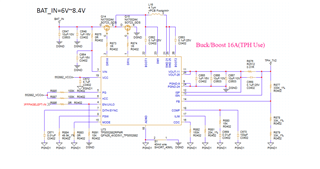
We are currently designing a circuit using the TPS552882, and would appreciate your help reviewing our schematic to ensure there are no obvious mistakes or issues.
Thanks!
This thread has been locked.
If you have a related question, please click the "Ask a related question" button in the top right corner. The newly created question will be automatically linked to this question.
Hi Bryce,
Thank you for your reply.
The part numbers for the MOSFET and inductor are SM333NHQG and PIC10040-4R7MA, respectively.
The load is a motor that draws nearly 10A at startup and stabilizes to an average current of approximately 1A.
Could you please help confirm whether the selected components are appropriate?
Best regards,
Tom
Hi Tom,
1.How long will 10A load last? With R876, output current limit is set to 5A. Recommend to short R876.
2.Recommend to add 100uF E-CAP in Vin and Vout.
3.I cannot find SM333NHQG. Can you provide datasheet.
4. Isat of inductor is only 8.5A. Recommend to change to a 16A Isat inductor.
5.Recommend to use 50V rated boot cap.
6.Recommend to add RC snubber in SW1 and SW2(2.2ohm+2.2nF first).
7.Recommend to add 0.1uF cap in Vin and Vout.
8.Make sure VCC has 2uF effective capacitance with 5V DC bias.
9.Recommend to connect VCC cap to DGND.
10.Follow layout guideline.
Regards,
Mulin
Hi Mulin,
Thank you for your reply.
The 10A load duration is approximately 500 µs.
Since the 10A load only lasts for 500 µs, is it still necessary to add 100 µF to the input and output capacitors, and to select an inductor with a saturation current rating of 16A in this case?
The MOSFET datasheet is attached.
SM3323NHQG_datasheet_package.pdf
Best regards,
Tom
Hi Tom,
500us is steady state to IC considering switching period, so it is necessary. MOSFET seems ok to me.
Regards,
Mulin
Hi Mulin,
Due to PCB size constraints, I’m unable to place E-CAP at the input and output. Instead, I plan to add 47 µF MLCC at both the input and output, and replace the inductor with one that has an Isat of 14 A.
Would this be acceptable, or do you have any other suggestions? Your advice would be greatly appreciated.
Best regards,
Tom
Hi Tom,
Adding a 47uF MLCC will help. Notice the effective capacitance of the MLCC, make sure it has large effective capacitance. Bench verification is needed.
Regards,
Mulin
Hi Mulin,
I also need PCB layout for TPS552882 this chip. Can you send me the files please. I sent you a friendship request.