This thread has been locked.

If you have a related question, please click the "Ask a related question" button in the top right corner. The newly created question will be automatically linked to this question.

UCC25660: LLC not working

Part Number: UCC25660
Other Parts Discussed in Thread: UCC25661

Tool/software:

Hi,

I posted this a while back :https://e2e.ti.com/support/power-management-group/power-management/f/power-management-forum/1495822/ucc25660-afpc-not-starting-working-ucc2818

But due to changing priorities i didn't manage to properly debug it .

here is the short version:

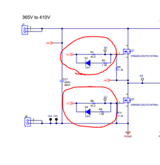
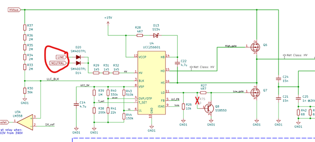
Mains -> filter + inrush limiting -> rectifier-> UCC28180DR APFC  -->  UCC256601 LLC

here is some of the progress i made: 

- APFC works if i have external ( isolated) 12-15V for the chip. ( not surprised since the LLC WAS supposed to provide that from an auxiliary it. APFC is within specs and it runs a bit cooler then i estimated/calculated

i didnt yet test it at max load

- on the LLC side there was a minimum capacitance on the auxiliary that i was not quite meeting but i fixed that on the prototype , the LLC aux now only supplies the LLC , so no more other variables/ extra consumers.

- the LLC chip is lukewarm , everything else is like room temperature while the UCC25660 like about body temperature or a bit higher.

From my measurements: the LLC aux 12-15V is stuck at 4.8-5V , that is also the voltage of the 5V used internally so I am not sure how to interpret this.

I also changed the chip once so it is very unlikely that both chips are bad in the same way.
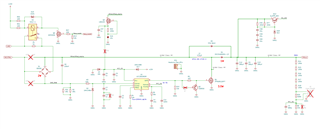
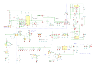
Schematics:

THX in advance for your help

  • D17 is removed , and i am using external power for the APFC as of now.

    Not sure why PNG looks blurry but after i click it it looks ok / clear.

    As for C21 C24 i tried with them in series like in the schematic or in parallel to GND like in some other reference designs but there seems to be no change in behavior.

    On the output i cant detect anything besides noise , i initially suspected the synchronous rectification but there is simply nothing coming out of the transformer.

  • Hi Dietrich,

    Could you debug LLC only by supplying high voltage DC input and VCC externally. Remove the aux winding diode. Also, could you connect the filter caps as mentioned below.

    Could you also connect the gate driver components as shown below.

    Please use the UCC25661 instead of UCC25660. We are planning to discontinue the UCC25660. They are pin to pin compatible.

    UCC25661 data sheet, product information and support | TI.com

    Regards

    Manikanta P

  • Hi Manikanta,

    Ok I will remove the AUX diode and provide isolated DC on that rail .

    Well i did that before but ended up burning the IC, i forgot the internals and Vcc current went through the HV regulator streight to bulk caps. This time ill provide HV DC then the AUX DC.

    As for the LL T_set OVP/OTP pins the configuration resistors are like right next to the IC and ill solder those caps on top of the resistors . I dont remember filtering caps in the datasheet but ill add them anyway . As for the voltage rating of those caps ill assume 5V and use 10-16V rated ceramics.  Is this good enough?

    Regarding the Mosfet gates yea i totally forgot to put a series element on high side one , ill see what i can make in air after i cut the trace. As for the other one yea sure i was thinking of doing something similar that is why i put that BJT there, there was an app note about this somewhere. I ll put a diode across the BJT and put try to math the rest of the values.

    Regarding the UCC25661 vs UCC25660 ok ill order some UCC25661 in the near future , and meanwhile ill see what i can do with the rest of the suggestions you mentioned.

    Best regards

  • HI Manikanta,

    Sorry for the late answer but some other stuff needed attention and i also had to wait for part orders.

    I added capacitors like you said and there was no it works moment.

    I didnt change the gate driver resistances , not yet, since i was trying to do changes in parts to see what is the thing that fixes it. 

    And connecting the gate drivers like you said requires some trace curing and then i need to graft in stuff, so i tried the easy fix first. Yea that was a MASSIVE/OVERSIGHT mistake on my part, I sort of though it was not needed at all since there was ZVS

    Ill try to do the driver resistor changes next week.

    So back to after the capacitors were added, nothing noticeable changed. I think the IC is a bit hotter now but that might be remembering stuff wrong. There is 0V on the 24V output and i also measured about 0.5V on C14 ( the capacitor on the 5V rail generated by the IC).

    I am also writing this now so that the thread does not get closed.

    Best regards

  • Hi Dietrich,

    We will get back to you by tomorrow.

    Regards

    Manikanta P

  • Hi, Please give VCC and High voltage DC externally and also give Line-Neutral AC in HV pin of IC  as shown in below and check V5P pin of IC if it is powering up to 5 V or not?

    If it is powering up, please check if you are getting any pulses in HO, LO pins of the controller or not !!!

    Regards,

    Sougata