This thread has been locked.

If you have a related question, please click the "Ask a related question" button in the top right corner. The newly created question will be automatically linked to this question.

LM5171: Channel 2 current limited to <1A

Part Number: LM5171

Tool/software:

Hi there,

sorry we tried to resolve the previous issue through a small board redesign but testing showed this issue wasn't solved at all.

What is supposed to happen

LM5171 is configured in DEM and shall boost 3.3 Vin and 5 Vin to the same 12 Vout, individually sinking up to 12 A at its input.

Problem:

Namely, CH2 only seems to not boost above a threshold under <1 A, last time it was 0.42 A, then 0.25 A, now under 0.5 A on the new PCB. CH2 was designed to be the exact copy of CH1, which happily boosts to 9+ A (didn't try higher but don't see why it could do it)

When varying ISET pin for CH2, the input current drawn first scales linearly as expected but quickly plateaus off. As in no matter what you set ISET voltage above, the current doesn't increase anymore at all and remains constant at this "plateau".

What we tried, and the result:

- 2x board redesigns, problem still persists

- half the Current sense resistor value by soldering another current resistor in parallel with the intention to plateau off at twice the current, plateau still appears at the same current as with one resistor.!

- flipping Channel 1 input and Channel 2 input with the intention to see if CH2 plateaus due to the low input voltage of 3.3 V. Instead, now CH1 can perfectly sink multiple Amps of 3.3 V and CH2 still has the same current plateau even with 5V from which it stops increasing in current.

In all cases, we have verified our Vin, Vout, ISET voltages and current measurements using multiple independent instruments.

What we haven't tried: Reading out LM5171 fault registers.

I have attached the schematics, .xlsx with the employed values, and a screenshot of the PCB. Do you see anything suspicious that could cause this plateau? Can't wait to send it off into production...

Thank you,

Karim

1057.LM5171 Buck or Boost Quickstart Tool_1.0.1.xlsxMA_tester_v1.pdf

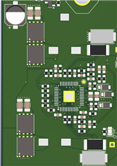
 Assembly drawing for a placement overview (LM5171 and SER1360-272 missing)

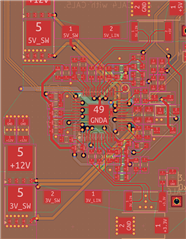
 PCB design showing the layout more clearly, with orange (for FET gate drive) being Layer 3.

  • Hi Karim,

    I will look into the schematic and design calc.

    Do you have any waveform?

    Best Regards,

    Feng

  • Thank you very much, Feng.

    I can hook up a basic 4-channel scope (no diff robe, but subtraction would be doable), what traces would be most helpful for you and under what testing conditions?

    Thank you!

  • We read out the Flags of the LM5171 which reports a fault for the Current limit Channel 2 while only sinking a few hundred milliamps.

    As a note; this happens with CH2 only, we can reliably sink 5-10 A on CH1 independent on whether the Input voltage is 3 V or 5 V. This issue has been shown on two different board designs using the same LM5171 stage. Both channels use the exact same hardware.

  • Hi Karim,

    Please check inductor current, SW2, ISET2 and COMP2 voltage so that we can confirm CH2 is operating with peak current limit.

    Best Regards,

    Feng

  • Hi Feng,

    have you ever tried replicating this setup in your labs (successfully)?

    only today could we run the test. Since I have no diff probe, I unfortunately couldn't measure inductor current. We tried measuring the voltage before and after the Rcs and use the subtraction function, but the resolution was not high enough to measure the voltage drop across a 4 mOhm resistor. I didn't take a screenshot, because the data was worthless and we needed to focus on getting it to run...

    SW2 showed the expected behaviour after a few hundred mA, then halving to the expected fsw and showing the known PWM shape.. Comp was mainly constant with a little jitter around every switching cycle if I remember correctly. Overall, totally saw expected behaviour and are really disappointed in this IC. Since CH1 works as expected, we wired two boards into one such that both inputs are each using a CH1 and finally got our test setup working. There are other weird issues occuring and we are now looking for a different IC that is reliable and behaves as expected. This is our first TI product that we cannot get to work no matter how hard we try, and for $7 per IC we expected more...

    Can we simply use any adjustable current limit boost IC? The LM5125 looks very exciting, but is nowhere in stock. Thanks.

  • Hi Karim,

    I cannot help you with descriptions only. Please share the waveforms. Please measure the current using a current probe.

    I am not able to replicating your setup as our EVM has only one LV input. But I don't think that makes much difference.

    The current can be limited by peak current limit. However, you may get two different average current for the two phases.

    You may find LM5125 from ti.com. Please contact TI local sales office if you need help on samples.

    Best Regards,

    Feng

  • Feng, thanks for your reply and I fully understand you. A current probe is requested and supposed to be in mail soon, though as stated the waveforms for SW and COMP looked as expected. Since we have little time, we proceeded designing our board with 2x LM5171 since we have experience how to get CH1 to work, and LM5125 is out of stock. It is easier to waste money on BOM than waste your and our time...

    But of curiosity, could you try use one of your EVMs, desolder the inductor from CH1 and test if you can boost from LV to HV side (thereby using CH2 only)? Maybe the HW config doesn't allow you to test our voltages (3.3V->12V) but maybe you can replicate the issue. That would be insanely insightful.

  • Hi Karim,

    I can check that on the bench. I will come back to you when I get the result.

    Best Regards,
    Feng

  • Hi Karim,

    I don't see any issue with CH2 when CH1 inductor is open.

    Best Regards,
    Feng

  • Ok, we believe to have found the issue!!!

    In our testing, we showed that if CH1 is Disabled and CH2 is Enabled, we can NOT boost at full power. We observe the issue as described in the original post. We could not find an issue in our PCB nor in our schematics and software, as we confirmed the desired states of EN1 and EN2 on the pins of LM5171 using a multimeter.

    Solution: Channel 2 boosts as expected, when both CH1 and CH2 are enabled.

    Is this a known issue with LM5171?

    The LM5171 was sourced from Mouser, we already purchased and received samples directly from ti.com, but haven't tried them just fyi.

    PS: I was possible to measure the Inductor current without current probe thanks to the IMON pins. We removed the filtering capacitor parallel to the resistor and observed a typical CCM waveform typical for inductor current.

    Steps we tried in this order :

    1.
    UVLO Hi

    2.
    EN1 Hi, ISET1 3A, works as expected
    EN2 Hi, ISET2 also 3A, works as expected
    All I2C flag as expected (OK)

    3.
    ISET1 0A, works as expected
    All I2C flag as expected (OK)

    4.
    EN1 Low, CH2 rail breaks down as described.
    Reading Flags: ILIM2 NOT OK

  • Hi Karim,

    I thought you meant EN1 and EN2 are high, and channel 2 doesn't work well.

    If EN1 is high and EN2 is low, channel 1 will switch. If EN1 is low and EN2 is high, channel 2 will not switch.

    Best Regards,
    Feng

  • Hi Feng, thanks for your message. What you wrote is exactly the behaviours we observed, but your information is not public until now.

    The observed behaviour clearly contradicts the Datasheet Section 6.3.5.1 "Channel Enable commands (EN1, EN2)" , and as one would assume given two separate EN pins: "EN1 controls CH-1, and EN2 controls CH-2."

    It's painful having designed three iterations of the board in hope to fix this error, having gone though all code and calculations just to find this bug in the chip.

    Thanks for your assistance though. We will close this issue after your final comment. Any further insight is welcome.

  • Hi Karim,

    Sorry for the confusion.

    We will add this information in the next datasheet revision.

    Best Regards,
    Feng

  • Hi Karim,

    I made a mistake on the EVM.

    On the EVM in buck mode with voltage loop, If EN1 is high and EN2 is low, channel 1 will switch. If EN1 is low and EN2 is high, channel 2 will not switch. This is due to the VSET is controlled by EN1.

    If you apply 2V to both ISET1 and ISET2, channel 1 and channel 2 can work independently.

    Best Regards,
    Feng

  • Hi Feng,

    thank you for sharing your findings. I am not sure what to make out of it - in our application, we use LM5171 in boost mode, have two different LV input voltages and boost to a common output by setting ISET via a Microcontroller. In that scenario, we tried to ENable only the channel we wanted to test, and as described had no chance to test CH2 independently until your clarification removed our doubts in our observation. Really really strange IC behaviour.. (I mean why bother have a EN2 enable pin).

    Anyhow, the next PCBs are arriving soon and we have wired EN1 and EN2 together. Thanks a ton for your support!

    Best,
    Karim