This thread has been locked.

If you have a related question, please click the "Ask a related question" button in the top right corner. The newly created question will be automatically linked to this question.

TPS23861: TPS23861PWR IEEE802.3 at & af setting problem

Part Number: TPS23861

Tool/software:

Hi Sir,

may we know some question as below:

1. Does the TPS23861 have a spread-spectrum feature for Power that can be optimized for EMI testing?

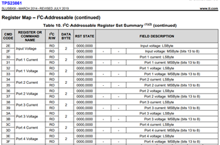
2. How can I read the current IEEE 802.3 at & af configuration of the MCU via I2C? Can I modify the settings myself?

3. How can I determine whether there is an OCP (Over-Current Protection) or OVP (Over-Voltage Protection) function?

4.What is the default standard that the LAN port will detect based on the MCU's preset configuration?

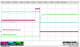
5. Currently our 10G PSE Sifos test fails at mark voltage min item of at mode. What does this part relate to? refer to the following file:

10G PORT1-AF Mode.xlsx

  • Hi Tommy,

    1. TPS23861 does not have switching function. Normally PSE chip won't be a cause for EMI issue;

    2. Yes you can read and write the TPS23861 registers by I2C. We also have reference code via www.ti.com/.../TPS23861  

    3. TPS23861 has Icut protection in 2A and 2B registers for OCP. No specific OVP, but you can read the input and port voltage by register

    4. TPS23861 is 802.3AT standard. You can select PHY (physical);

    5. The fault is expected since TPS23861 is AT rated and will show two Class events for Class-4 PD. Correct way is either test with AT 30W, or disable the 2nd classification for AF only (see below link)

    https://e2e.ti.com/support/power-management-group/power-management/f/power-management-forum/723204/faq-tps23861-how-to-configure-to-output-type1-power-even-if-a-type-2-pd-is-connected

    Best regards,

    Diang

  • Hi Diang, 

    Thanks for help. Could you please share more detail about how to "disable the 2nd classification for AF only"? Besides, what's the standard testing process for SIfo mark voltage min?

  • Hi Wayne,

    Please check below about "disable the 2nd classification for AF only":

    "

    If TPS23861 discovers a Type 2 (class 4) PD is connected during the first finger classification, the PSE should initiate a second finger classification and set the ICUT to 645mA which enables Type 2 power.

    However some customers want to limit the port output power to Type 1 even a Type2(class 4 ) PD is connected due to power management or load power limitation. It can be implemented by disabling two-event classification (0x21h) and setting ICUT to 374mA (0x2A, 0x2B).

    "

    Class 4 mark voltage passing range is 7 - 10V. For Class0-3 with only 1 classification, mark may not be needed.

    Best regards,

    Diang 

    • Hi Diang, 

      Thanks for feedback. Actually the design is for both AT and AF. For AF, we will try to disable the 2nd classification. However, how about AT mode? Our design include 4 ports AT and there is a 10G port with this issue. The mark voltage is only 6.7V. Is there any way to increase it?

    • Hi Wayne,

      It could be caused by some diodes added in the port in series. Could you share the schematic? 

      Best regards,

      Diang

    • Dear Diang

      The SCH as below

      About AT mode faild item, we have try to modify PSE output voltage from 53.5V to 54.8V, it look can pass mark voltage faild item,

      that is correct solution or just workaround ? 

      and we found another test item, and the instrument determined it as 'info'. Can you help me check it? How should I resolve this?

      Sifos suppliers believe we need to solve this issue to avoid other impacts.

      thanks

      best regards 

      Howard

      GPT-5340KV1_C2_AA_PSE circuit_20250610.pdf10G PORT1-AT.xlsx

    • Hi Howard,

      "Info" is not a failure and normally do not need to make changes.

      About AT mode faild item, we have try to modify PSE output voltage from 53.5V to 54.8V, it look can pass mark voltage faild item,

      that is correct solution or just workaround ? 

      I did not think the PSE output voltage (Vpwr) and Vmark has a strong connection. After checked the schematic, there is no diode in series to cause a voltage drop and insufficient voltage. My guess is the channel MOSFET (SSPR18N10-C) has low threshold in range of 1 - 2.5V. Thus it could be harder for the GATE pin to control the MOSFET and output a low port voltage like 7V for mark accurately. The recommended characteristics are shown in below:

      • Vth(gs) min > 2 V
      • Rds (on) : 50mohm ~ 150mohm at Vgs =10V
      • Ciss : less then 2000pF
      • Qg : less then 50nc
      • BVdss : larger then 100V

      Best regards,

      Diang

    • Dear Diang

      So, can I think my project AT mode and AF mode standard test are all pass right?

      If no show FAIL item on Sifos test report.

      Could you share why I need to choice NMOS spec Vgs(th) > 2 V ?

      I want to leran it.

      thank you~~

      thanks

      best regards 

      Howard

    • Hi Howard,

      So, can I think my project AT mode and AF mode standard test are all pass right?

      If no show FAIL item on Sifos test report.

      I agreed if it is a passed report with no failure and all necessary items are tested. 

      Could you share why I need to choice NMOS spec Vgs(th) > 2 V ?

      The Vport = Vpwr - Vds, Vpwr is the ~54V stable DC voltage and Vds is the FET drain-source voltage can be adjusted by TPS23861 gate drive. During handshake times, Vport is below 20V and the Vds is normally 50 - 30V which means the FET is in saturation region (Vgs is closed to Vgs_th) by GATE pin's fine tune of sink & source current.

      If Vgs_th is low as ~1V, for some MOSFETs with very sensitive channel inversion layer, the gate driver could be hard to control the Vds to produce an accurate Vport. 

      Best regards,

      Diang

    • Dear Diang

      Do you know where can downlaod TPS23861 themral simulation file setting ?

       .ibs

      this is for simulation can import somthing themral data to simulation.

      Thanks

      Best Regards

      Howard

    • Hi Diang

      Do you know if I need to verify OCP function on TPS23861

      Which Pin can be trigger OCP function waveform?

      Best regards

      Howard

    • Hi Howard,

      Sorry we do not have TPS23861 thermal mode. You can refer the package and thermal resistance in the datasheet.

      An OCP or Icut event will be recorded by register.   

      Below is one example of OCP waveform 

      Best regards,

      Diang