This thread has been locked.

If you have a related question, please click the "Ask a related question" button in the top right corner. The newly created question will be automatically linked to this question.

LM5171-Q1: Oscillation on the Vset pin as a function of the operating point. Regulation instabilities

Part Number: LM5171-Q1
Other Parts Discussed in Thread: LM5171

Tool/software:

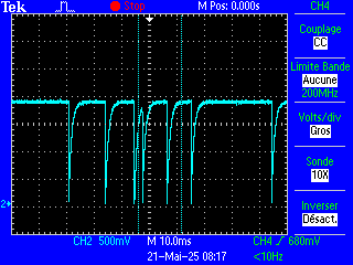
I'm observing oscillations on the Vset pin of the LM5171 circuit depending on the average level I set on this pin: when the level is below 1.5 V, bulk mode works perfectly and the regulation is correct. However, above 1.5 V on the Vset pin, I start to observe oscillations on this input and, consequently, on the LV output. 

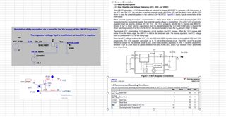
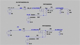
I suspect there are value errors on some components. Which components are sensitive in the regulation feedback loop? For my design, I followed the advice provided in the spreadsheet "LM5171 Buck or Boost Quickstart Tool_1.0.1.xlsx".
In my design, the Vset voltage is fine-tuned using a DAC coupled by a 100k resistor to the voltage divider connected across the Vref voltage.

Here are some questions:

  • What happens when the chopping inductance value is very high? Can a high inductance value cause unstable regulation?
  • I limited the peak current by setting the IPK pin to 0.4 V. Could this setting be causing the regulation instability?

Attached are the settings used.

2548.LM5171 Buck or Boost Quickstart Tool_1.0.1.xlsx
Thanks in advance for your help

Regards,

Bruno

.

  • Hi Bruno,

    I guess some error is seen and the IC is restarting, like OVP.

    Can you check SS/DEM pin?

    Best Regards,

    Feng

  • Hi Feng,

    I found an explanation for my problem: it's due to the voltage level on the Vcc pin. In my design, Vcc is 8.8 V, which is too low according to the datasheet.

    To obtain the equipotential of Vcc, I followed paragraph 6.3 of the datasheet using an NMOS transistor. When I noticed that the Vcc voltage wasn't high enough, I simulated this part of the schematic. The simulation confirmed the observed results.

    Here are my questions: What type of NMOS transistor do you recommend to bias Vcc? I couldn't find the typical voltage level of the LDODRV output pin in the datasheet. Which one?

    What do you recommend to solve this problem?

    Thank you very much for your help.

    Bruno

  • Hi Bruno,

    The only limit is Ciss<300pF as suggested in the datasheet.

    You may use PMT560ENEAX which is used in the EVM.

    Best Regards,

    Feng

  •  Hello,
    Thank you very much for your reply. I don't understand why the input capacitor has such a significant impact on the operating point of the bias, which is static.

    I performed a bias simulation with the transistor you recommend, and the result depends on the input impedance of the Vcc pin. This simulation is consistent with my observations on the actual board. Even with a relatively high input impedance (10kohms), we observe that the regulated voltage is insufficient to power the LM5171 component.
    Do you think this simulation is unrealistic?
    To refine this simulation, could you provide me with two additional pieces of information: what is the input impedance on the Vcc pin? What is the expected voltage on the LDODRV pin of the LM5171 component?

    Attached, you will find the LTSPICE simulation of the bias function.
    Thank you in advance for your answers.

    Bruno

  • Hi Bruno,

    LDODRV is regulating VCC to 9V. So, LDODRV voltage is changing based on VCC voltage.

    For loop stability considerations, Ciss is limited.

    Best Regards,

    Feng

  • Hi Feng, 

    Sorry, but I don't understand your answer. I ran my simulation with the appropriate PMT560ENEA MOSFET. The simulation is consistent with what I observe on my board. I also measured the current flowing on the Vcc pin. On my hardware board, the current on Vcc is about 100 mA. This seems correct. This corresponds to an equivalent 100 ohm load. With such a load, the simulation shows that the output voltage on the source pin cannot exceed 8.2 volts, which is insufficient. Did I miss something?
    Thanks for your feedback.

    regards,

  • Hi Bruno,

    LDODRV pin is not providing a fixed voltage. It will go higher if VCC<9V till VCC reaches 9V.

    Best Regards,

    Feng