Other Parts Discussed in Thread: BQSTUDIO, EV2400, GPCRB, GASGAUGECHEM-SW
Tool/software:
Hello,
I refer you to my main quastion that didn't solve my problem, but it's close.
link: e2e.ti.com/.../bq28z610-device-fw-unexpected-charging-cutoff-behavior-on-bq28z610-in-1s2p-li-ion-ups-design
Thank you for sharing the documents— they were very helpful. I have successfully completed the learning cycle, and I can confirm that the RA table has been updated. Additionally, cell balancing (BAL_EN) is now enabled.
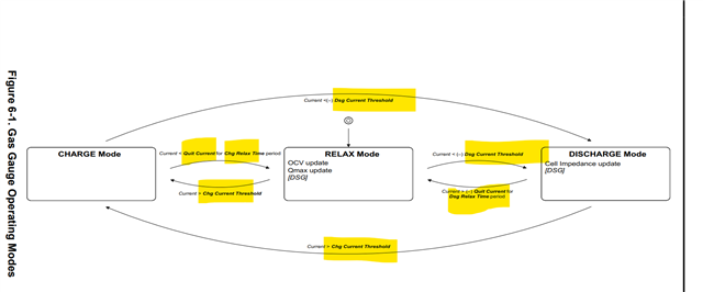
However, I noticed that the IC operates in only one mode at a time—either charging or discharging—depending on the command sent. When the charging command is issued, the IC stops balancing. Is this expected behavior?
Since I am using the IC in a UPS application, I need it to support both charging and discharging simultaneously. Could you please advise on how to enable dual-mode operation?
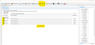
Also, I attempted to generate the "Golden Image" file, but an error message appeared during the process. Could you help me troubleshoot this issue?
Best regards,
Tarek Sharbo