This thread has been locked.

If you have a related question, please click the "Ask a related question" button in the top right corner. The newly created question will be automatically linked to this question.

BQ25798: Not able to charge battery beyond 4A

Other Parts Discussed in Thread: USB-PD-CHG-EVM-01, TPS25750, BQ25790, BQ25798, BQ25792, TPS25751

Tool/software:

Using a USB-PD-CHG-EVM-01, I am trying to charge a 4 cell LiFePO4 battery with 5A.

Not able to go beyond 4A, no matter the battery discharge level, power source or sink selection, battery charging voltage on the application.

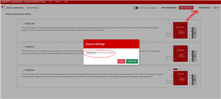
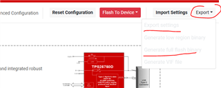
I'm using TPS25750 Application Customization Tool.

Power source: tried 60W and 100W options

Powers sink: tried 60W and 100W options

Preferred power role: Power sink

USB speed: tried No USB data, and USB2 options

Preferred Data role: tried "no" and Host & Device Role Port (DRP) options

Charger selection: picked "BQ25790 or BQ25792" option -although EVM has a BQ25798, it's not in the options-

Battery charging current: 5A

termination current: 0.4A

pre-charge current: 0.4A

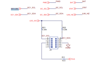
Jumper for 4 cells is shorted. I tried also "shorting the ILIM_HIZ to REGN pin to set the maximum input current limit" as per data sheet ILIM_HIZ pin description notes

WHAT AM I MISSING?

Thank you!

  • Hello Iz,

    Can you provide configuration file?

    Best Regards,

    Christian

  • Hi Christian,

    Thank you for the response. I tried inserting files by drag-drop. It seemed to happen but I can't see the files attached.

    Please let me know how I can attach files.

    Regards,

    Iz

  • Hi Iz,

    Typically you can just insert the json files by dragging them from file explorer to the message tab.

    There is also the insert option.

    Do you have a TI sales contact?

    Thanks and Regards,

    Chris

  • Hi Chris,

    I ordered and received a 2nd UB-PD-CHG-EVM-01 thinking there might have been an issue with it; but the 2nd unit came with a 512kB Flash chip instead of a 256kB. I now can't use the bit files generated by the TPS25750 Application Customization Tool, as they are generated for 256kB Flash, but no option in the tool for 512kB Flash. 

    My first EVM has 256kB Flash, and it does the sink negotiation and I was able to charge the battery, although never to 5A.

    With this 2nd unit I'm NOT able to even negotiate sink power. No 20V input, therefore no charging.

    How do I generate 512kB compatible "Full Flash Binary" files from TPS25750 Application Customization Tool?

  • Hi Iz,

    The CHG-EVM has been updated to ship with the TPS25751, the direct successor to the TPS25750. You can confirm this by checking the markings on top of the PD IC (U4). We are working on updating the documentation to reflect the new IC.

    You need to use the GUI found on this page: https://www.ti.com/product/TPS25751

    I would recommend using V1.0.2, and make sure to select "TPS25751" when making the config.

    Here is a basic json that you should be able to use in this GUI for the CHG-EVM that can get you started.

    {
      "questionnaire": {
        "device": "TPS25751",
        "toolBuildVersion": "1.0.2",
        "answers": [
          null,
          0,
          2,
          3,
          1,
          0,
          3,
          0,
          1,
          1,
          1,
          0,
          0,
          0,
          12,
          3,
          0.4,
          0.4,
          0
        ],
        "vendorId": "0000",
        "productId": "0000",
        "version": "1.0.0.2"
      }
    }


    The first CHG-EVM you have probably has the TPSTPS25750. The two parts (750, 751) do not use the same binaries.


    Regarding the initial question for charge current:

    The json provided is configured for a 3s battery and the charge current is set to 3-A. You will need to update it for the settings you desire.

    There can be many reasons why the battery will not charge at 4-A as there are many limiting factors.

    1. The charge current is set to a value <4-A. In this case, update the charge current field in the GUI to 4-A
    2. The adapter you are using cannot provide enough power.
      1. In your system, it sounds like you are testing at 4s and want 5-A. Let's say the battery is at 15-V, so this would come out to roughly 75-W
      2. If the USB-C PD adapter connected is not >75-W capable, the system should limit charging. The PD controller will negotiate a PD contract to some power level and will program the BQ to not draw power in excess of that negotiated level.

    If you have a PD analyzer, it would be useful to see what PD contract is negotiated.

    If you have the adapter being used, it should say what USB-C PD contracts it supports. You can measure the VBUS voltage to see what voltage is being negotiated.

    In addition, for >3-A PD contracts, specific cables that support >3-A are needed, so there is also the potential that the system is being limited by the cable capabilities.

    Thanks and Regards,

    Chris

  • Hi Chris,

    I have been using this tool:

    First, I want to ask: Do I need json file or bit file to program the Flash? The tool I was using generates a bit file.

    I fill in the questionnaire and I click "Generate a Full Flash Binary" button. The tool generates a 32kB bit file, then I use Total Phase Aardwark tool to send this bit file to the Flash. 

    As for 3s vs 4s selection, I don't see that selection in the config questionnaire. I checked the new one you suggest, but I don't see this cell selection there either. What am I missing?

    I have verified my USB C PD adapter and the cable is capable of 100W, 20V/5A.

    Thank you,

    Iz

  • Hi Iz,

    As mentioned before, the CHG-EVM was recently updated to ship with the TPS25751 IC, which is the latest version of the TPS25750. It sounds like you have two evms, one with the TPS25750 and another with the TPS25751. Unfortunately, you need a new GUI to use the TPS25751.

    The TPS25750 is not recommended for new designs, and all new designs should move to the TPS25751.

    The tool you currently have is good for the TPS25750.

    You should use v1.0.2 for the CHG-EVM with the TPS25751. That GUI can be found here: https://dev.ti.com/gallery/info/USBPD/USBCPD_Application_Customization_Tool/.

    Do I need json file or bit file to program the Flash? The tool I was using generates a bit file.

    You need the binary file to program the Flash.

    The Json allows you to save the current state of the GUI so you can reopen the GUI at a later point with the same settings. You cannot populate the GUI from a binary file.

    To load the json I shared with you into the GUI, download the json, open the GUI, and import it using the "Import Settings" button.

    If you make any changes to the gui, you can save your current progress with the "Export->Export Settings" button where it will prompt you for a file name and location for a json of the current GUI settings. The GUI questionnaire needs to be completely filled out in order to export any files.

    I fill in the questionnaire and I click "Generate a Full Flash Binary" button. The tool generates a 32kB bit file, then I use Total Phase Aardwark tool to send this bit file to the Flash. 

    Correct, in the new GUI, you use "Export->Generate Full flash binary" to do the same. 

    As for 3s vs 4s selection, I don't see that selection in the config questionnaire. I checked the new one you suggest, but I don't see this cell selection there either. What am I missing?

    There is no question specifically for 3s/4s. I was referring to the Battery Charging voltage field (q10). In the json I shared with you, the battery charging voltage is set to 12-V(3s). You may want to change this value if you are testing with 4s.

    Do you have any tools that can read/write I2C? Once you get the new CHG-EVM working, we may need this to continue the 5-A charge current debugging.

    Thanks and Regards,

    Chris

  • Hi Chris,

    I just checked U4 on my EVM, it is TPS25750. (I have returned the board with 512kB Flash I mentioned earlier, which was probably TPS25151 -I didn't check).

    I will now use the V1.0.2 and generate a new bit file for TPS25750 (using TPS25750 option) and will let you know of the outcome.

    I am using the Aardvark tool to write I2C to the Flash, does that count as a debug tool that you're asking?

    Can you do me a favor and send me 2 bit files made for TPS25750 (NOT 25751):

    1)  100W source, 100W sink, preferred method: sink, No USB, chg Voltage:14.6V, 5A, Chg term: 400mA, Pre-Chg: 400mA

    2) 60W source, 60W sink, rest is same as above.

    I'm  open to suggestions on the parameters, especially the charge voltage.  Bottom line is: I need 5A charge current on a depleted 4 cell Lithium Ion Ferro Phosphate chemistry.

    Thank you,

    _Iz

  • Hi Chris,

    Update: No difference with the new bit file generated by the new tool. The Input (20V) current seems to be stuck at max 3A which indicates 60W. The charge current is max 4A.

    When I load the system with 5A load, the PD is not able to provide the whole 5A, which, it should be able to do if 100W has been negotiated. The charger IC (BQ25798) stops charging and  has to divert some of the power to the load from the battery. ~4A from PD, ~1A from battery. I think this is proper function for the charger IC, but I need the PD to be able to provide 5A to the load and when the load is not present, charge the battery with 5A.

    As I stated earlier, I have verified my PD & cable set with a PD tester (PassMark PM110), it is able to do 20V 5A.

    I understand that you are in Central time zone and I am in Pacific, but do you think we can do a phone chat on Monday June 2nd? Please let me know.

    Thank you,

    _Iz

  • HI Iz,

    I won't be able to get on a phone call today. Maybe Wednesday if you are free?

    I just checked U4 on my EVM, it is TPS25750. (I have returned the board with 512kB Flash I mentioned earlier, which was probably TPS25151 -I didn't check).

    Ok, as mentioned before, we do not recommend the TPS25750 for new designs. It should be able to negotiate 5-A charging though.

    I am using the Aardvark tool to write I2C to the Flash, does that count as a debug tool that you're asking?

    I'm not sure. Are you able to capture I2C logs with the Aardvark? If yes, or if you have another tool that can, could you capture the I2C traffic on power up and on connection of a Type-C source? I need to confirm if the PD controller is programming the correct values to the BQ device.

    I'll try to send you the binaries later today.

    Thanks and Regards,

    Chris

  • Iz,

    FYI, I got this information from the team that supports the BQ parts.

    The CHG-EVM is limited to sourcing 45-W due to thermal issues. There may be similar issues at high sinking power as well. The CHG-EVM DS says the EVM is only designed to do 45-W source and 66-W sink, so it may not be able to test the full range you are requesting.

    Thanks and Regards,

    Chris

  • Hi Chris,

    I will try to capture I2C logs but it will take time, as I need to familiarize with the tool. If you could, please send me the 2 bit files that I requested, I will test to see if the behavior is different.

    Question on the 66W-sink: Does the EVM anticipate the 5A charge will be more than 66W and therefore ignores the 5A value from the register? Or does it attempt to start the charge at 5A and goes into limit after it gets into thermal protectionMy EVM starts even at 2A for a few seconds then goes to 4A, does not attempt 5A at all.

    I put a big fan on top of the EVM, it helps to bring the IC temp down significantly, from ~70C to ~ 40C but still did not charge beyond 4A.

    Question on the Input Current Limit: I noticed a "input current limit" parameter mentioned in one of the registers. Can you please elaborate on what it does actually?

    Thank you,

    _Iz

  • Iz,

    Unfortunately I do not have one of the old EVMs with the 750 working. I only have new ones easily on hand, so did not get a chance to test this binary, but I configured it with the settings you asked for.

    If it makes sense, I would recommend evaluating with the TPS25751 as the TPS25750 is NRND, so it might make sense for you to keep the new EVM.

    My understanding is the power limits (45-W source and 66-W sink) are primarily thermal and layout related, so the board may work for a short period at higher powers.

    Here is a json with 45-W source, 100-W sink, with the settings you mentioned.

    When you test it, can you report:

    VBUS voltage when the adapter is connected.

    With the Aardvark connected to J3, can you use the Control Center software to read these TPS25750 registers and report what you read?

    • 5 bytes from Active Contract RDO (register 0x35)

    https://e2e.ti.com/cfs-file/__key/communityserver-discussions-components-files/196/TPS25750_5F00_CHGEVM_5F00_100WSink.bin

    Thanks and Regards,

    Chris

  • Hi Chris,

    Thank you for the file. I will test and let you know. Unfortunately I have already returned the 751 EVM, I will have to work with what I have.

    I will try reading the registers directly and report to you also.

    I have 3 questions:

    1) Does TI provide the USB-PD-CHG EVM schematic in native format? Altium is preferred.  That would save me a lot of development time.

    2) Does 751 version have a different size Flash? If yes, I'm hoping it is the same footprint as 750's Flash. Just the size of the bit file is different. Yes?

    3) This is more of a statement. TI does not advertise USB-CHG-EVM with TPS25751, and it is confusing to have 2 different versions of the EVM with different size Flash ICs but  with the same name. Also not advertised is the Configuration tool version that you have specified. I wasn't aware of the version that handles 751 until you pointed out.

    Thank you Chris, I will let you know of the outcome of the bit file soon.

    _Iz

  • Hi Iz,

    1) Does TI provide the USB-PD-CHG EVM schematic in native format? Altium is preferred.  That would save me a lot of development time.

    Let me check internally. My team is not directly responsible for the board files.

    2) Does 751 version have a different size Flash? If yes, I'm hoping it is the same footprint as 750's Flash. Just the size of the bit file is different. Yes?

    Yes and no. We currently recommend a different flash because we thought we needed a larger (512 vs 256kb) flash, but recently did some work so that the TPS25751 patch bundle fits inside the 256kb flash. So technically, no, it does not have a different flash. But, the Datasheet still currently recommends the 512kb flash (and that is what is on the updated CHG-EVM schematic) so officially we recommend the larger one. The footprint is the same.

    3) This is more of a statement. TI does not advertise USB-CHG-EVM with TPS25751, and it is confusing to have 2 different versions of the EVM with different size Flash ICs but  with the same name. Also not advertised is the Configuration tool version that you have specified. I wasn't aware of the version that handles 751 until you pointed out.

    Correct, the update was fairly recent, and we are actively in the process for updating the document and product page with all of this information. Apologies for the confusion here.

    Thanks and Regards,

    Chris

  • Thank you Chris, for the detailed explanation.

    I have tested your bit file, got the same results. I have not yet been able to read the registers as you've suggested. The effort needed does not fit my schedule right now, I will circle back to it later in my development.

    Your explanation is sufficient for me to start the capture; Have you gotten a chance to check for me on the EVM schematics in native form, i.e Altium?

    Thank you again, for your guidance. I would like to keep this thread with you active for questions during my development cycle. Is that okay?

    Regards,

    _Iz

  • Hi Iz,

    Let me check with the team again on the EVM schematic, I still have not fully heard back.

    I would like to keep this thread with you active for questions during my development cycle. Is that okay?

    No, could you instead submit new E2E's, but use the "ask related question button"? You can also specify you worked with me. Typically we try to keep threads isolated to specific issues for tracking purposes and want to avoid E2E threads for generic support.

    Thanks,

    Chris

  • Hi Iz,

    See the altium schematic file attached.

    CHG-EVM Altium Schem Files.zip

    Thanks and Regards,

    Chris

  • Thank you very much for your help Chris!

    I will do as you suggest.

    _Iz