This thread has been locked.

If you have a related question, please click the "Ask a related question" button in the top right corner. The newly created question will be automatically linked to this question.

UCC28950: UCC28950

Part Number: UCC28950

Tool/software:

Hi, 

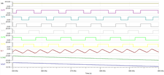
I am working on Phase Shifted Full Bridge Converter topology by using UCC28950. I have read "slua560d" document and used "sluc222e" excel. When I use TINA to simulate my values, output voltage is decreasing and the value is not equal to my goal. I am sending my TINA and Excel files. How can I solve this problem. I am also sending the graphic which have problems.

I want to 28V output voltage from 270V input voltage (1kW).

Best regards. 

PSFB.TSC     

SLUC222E.xlsx

  • Hello,


    If your output voltage is dropping and not regulating at your voltage something is not correct in your design or something is not behaving as you expect.


    When you use the excel tool for component selection you need to selected components within +/- 5% of the calculated values. I recommend that you check your schematic vs the excel tool to make sure everything is in these recommended values.


    Things that could cause your design not to regulate.

    1. Transformer turns ratio is not correct
    2. LS might be too big
    3. Current Sensing/Current Transformer is not setup correctly
    4. Feedback circuitry is not setup correctly


    Once you have verified that everything is correct.  I would trouble shoot this like a regular supply.  I would start by evaluating the voltage across the transformer, CS, the voltage amplifier output and the output voltage in your simulation.  This will help you figure out what is causing your output voltage not to regulate.  Once you have determined that it will be easier to fix your simulation.


    Regards,

  • Hi,

    After calculating everything one by one by reading from application note, I verified it with excel file. According to transformer leakage, there is no need to put Ls as 1.1 uH and leakage, but according to my calculation, Ls+Lpk total is enough if it is 3.9 uH. When I put a Ls bigger than that, the exact opposite of what should happen happens and my output voltage increases. I changed the value of everything from the ready file on your website and did not change the circuit at all. I tried all the changes you said before but it did not work, you will see that all the values ​​are compatible with excel

    Best regards

  • In addition, when I increase my transformer leakage (about 20 uH), the voltage level is increasing but the transformer has 1.1 uH leakage inductance and it is ready now.

  • Hello,


    That is puzzling.  Something in your circuit is just not behaving correctly.


    You should study the voltage amplifier output, CS and the transformer input, transformer output voltage and output voltage to try to figure out why your output voltage is not regulating in your simulation.


    If your output voltage is low the voltage amplifier output should be high demanding maximum duty cycle.  There is something in your design preventing the comp pin from going high or the output voltage from going higher.  Studying the recommended probe points should help you determine what is wrong in the circuit.


    Regards,