This thread has been locked.

If you have a related question, please click the "Ask a related question" button in the top right corner. The newly created question will be automatically linked to this question.

TIDM-02013: Huge explosion on the PCB

Part Number: TIDM-02013

Tool/software:

Hello,

While testing the PCB with my colleague Sebastián (who has posted a few posts on this forum), a large explosion occurred on the board and a subsequent fire broke out.

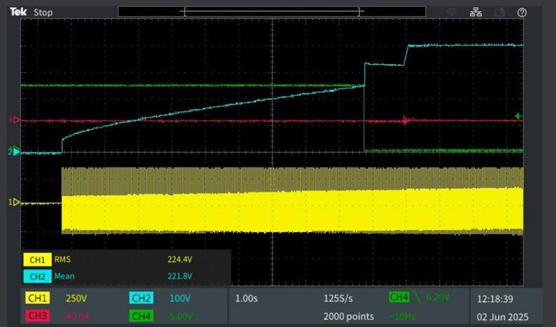
The board was working fine before with some problems on the control loop parameters, so we could discard a big problem with the PCBA assembly. Here the pics of the board fired.


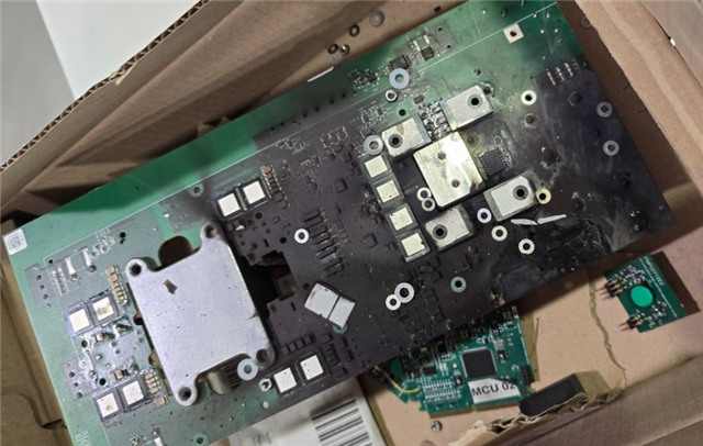
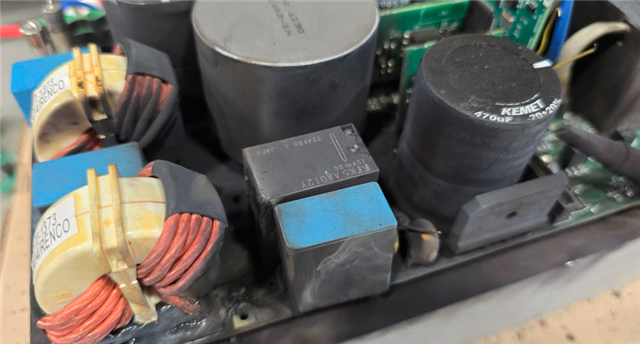
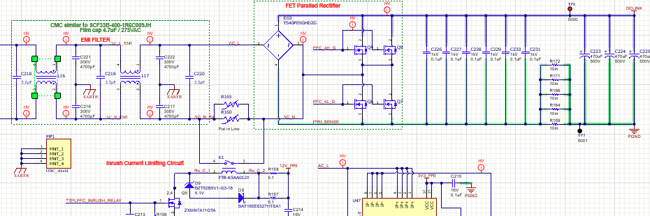
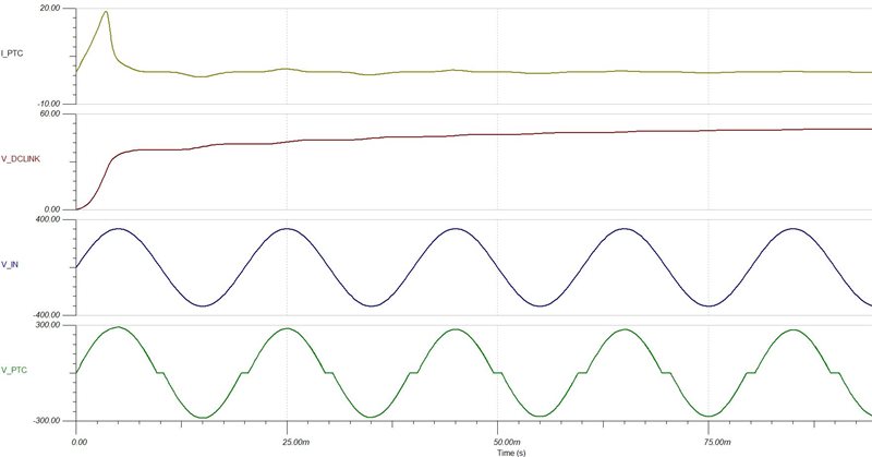
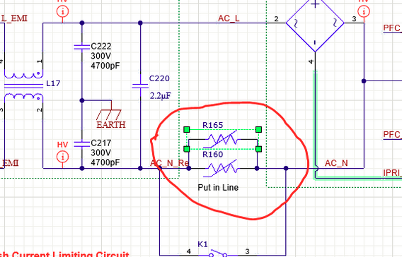
The explosion started in the PTCs (R160 and R165), and then the rest of the board caught fire.

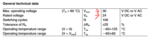
Analyzing these components, we see that they are 24V DC/AC and a maximum of 30V DC/AC, when these components are actually connected to the 230VAC input. Therefore, it's quite understandable that this component exploded. Here a screenshot of PTC  (B59101P1080A062) in the schematic and datasheet of the part number :


A design error seems obvious. Does Texas Instruments have any explanation for this incident?

Regards

Juan Carlos

  • Hello,

    I have looped in the expert from the team, and they should get back to you with a response in the next 1-2 days.

    Best Regards,

    Delaney

  • Hello Delaney

    Thank you very much. I look forward to hearing from you as soon as possible due to the importance of the matter.

    Best Regards.

    Juan Carlos

  • Hi Juan,

    While waiting for our HW design experts to comment further, could you please tell us when exactly this incident happened? This would help us to understand what went wrong.

    The PTC is not to block the AC input voltage and  230V AC input could not be the reason for this incident.

    1. May I know at what power did you run this experiment? What's the output voltage and Current?

    2. How long after powering up this board did this incident occur?

    3. Was the relay K1 connected parallel to this R165, R160 is closed prior to applying any load on the output?

    Thanks

    Srikanth

  • Hi Srikanth,

    The PTC is acting because, in a transient state, when the board is initially connected, the DCLINK capacitors (C223, C224, and C225) act like a short circuit (low inpedance). The chokes (L16 and L17) also have very low impedance, so almost all input voltage falls across the PTCs until the relay is activated. Here schematic:

    I have done a simulation with TINA and it confirms what I am saying:

    As you can see in the simulation, until the Relay is activated, in the PTC there is a lot of voltage, more than 24V recommended by the manufacturer. So probably this is the cause of the fire.

    To answer your questions:

    1. The voltage that we are testing is 230V AC, and the DCLINK voltage was about 400V with a 500R load on the DCLINK.

    2. After a few seconds.

    3. The relay was probably not activated, since our firmware didn't activate the relay until the TTPLPFC_VAC voltage was above 200VAC.

    This is how our FW was when the board exploded.

    I await your news as it is very urgent.

    Regards.

    Juan Carlos

  • The PTC will only get damaged when AC is applied and a load is on the DC link prior to turning on the converter. In this case the PTC will overheat and will explode. The PTC is not designed to operate under sustained current flow. In short you cannot apply a load the DC link until the inrush event is over and the relay is closed.

  • hello Brent,

    I don't know if I explained myself correctly, but during the board's startup, there was no charge on the DCLINK. The current that burned the PTCs was the current generated when the DCLINK capacitors were charged through the PTC (no load on DC LINK connector).

    We connected the 500R load after the relay had already been activated during normal testing.

    I'm attaching a screenshot of the osciloscope before the explosion:

    As you can see, the signal on CH1 is the input voltage (230 VAC).

    The signal on CH2 is the voltage on the DCLINK that is charging without any load on the DCLINK. If there had been a load, this signal would not be ramping up.

    The signal on CH3 is the input current. As you can see, it is very low, with only current spikes of a few mS during charging of the capacitors.

    The signal on CH4 corresponds to the relay activation. When this signal drops to a low level, the relay is activated.

    It is clearly seen that during the charging of the DCLINK capacitors for a few seconds the voltage on the PTCs is much higher than 24VAC and this clearly damages these components.This is confirmed by both the simulations carried out in Tina Space and the oscilloscope captures.

    Please tell us what happens to your board when it's powered by 230V and the relay doesn't activate until the DCLINK capacitors are charged (no load on the DC LINK). Can you please run this test for us please?

    Note that previously in the experiments we performed earlier, the relay was activated instantly when the board was connected to 230 VAC and this triggered the magnetothermal and differential switches due to high current peaks, this is why the tests we performed involved delaying the relay activation to gently charge the capacitors through the PTCs but doing these tests the board exploded.

    Regards

    Juan Carlos

  • Hi, Juan Carlos,

    I've powered the board up well over a 1000 times with 230 VAC. The only time the relay has every failed is when I have applied a load to the DC link prior to the relay closing. If AC is applied to the input when the relay is open and there is no load on the DC link I have never observed an issue with the PTC.

    Best regards,

    Brent

  • Hi Brent,

    Thank you very much for the information. I have a few questions:


    * Do you connect the board to some kind of grid simulator or directly to the grid (230 VAC)?

    * Do you have a screenshot oscilloscope showing how long it takes the relay to activate once you connect the board to the grid?

    * If you don't have a capture, can you tell me how long it takes for the relay to activate once you connect the board to 230 VAC?

    Best regards.

    Juan Carlos

  • Hi, Juan Carlos,

    During my tests I connected the the input to an AC source.

    Sorry, no I don't have this. The last time I checked the relay was activated based on the CCS command to start the PFC. It was not activated based on any voltage monitoring. The code could be modified to do this but I don't believe this was ever done.

    Best regards,

    Brent

  • Hi Brent,

    Can you try measuring how much time takes between the board is powered up and the relay is activated? Would that be very helpful?

    I still think that from the moment we power the board until the relay is on, during that time, the PTCs are energized with 230 Vac, as demonstrated by the attached simulations. Could you please give me your opinion on this?

    Best regards,

    Juan Carlos

  • Hi, Juan Carlos,

    I no longer have access to the hardware to run any new tests.

    All, I can tell you is that I have powered the board up countless times without any issues. However, there have been times when I forgot to turn off the load before applying AC. In those cases the PTC will fail in a manner consistent with what you reported.

    Best regards,

    Brent

  • Hi Brent,

    Okay, I won't bother you any longer. Last question I just ask you to look at this simulation and give me your opinion. As you can see, the voltage across the PTC at the beginning is very high, as we have almost 600 Vpp when the PTC is actually 24 Vac. This could never work... dont you agree?

    Best regards.

    Juan Carlos

  • Hi, Juan Carlos,

    I'm not really familiar with your simulation so I can't really comment on it. As I mentioned the only time I have seen a PTC failure is when the load is applied before the relay is closed. I've found this limiter (B59451C1130B070) to be much more robust. In new designs I would recommend using the  B59451C1130B070.

    Best regards,

    Brent