This thread has been locked.

If you have a related question, please click the "Ask a related question" button in the top right corner. The newly created question will be automatically linked to this question.

TPS1HTC100-Q1: Question about applying PWM signal to EN pin

Part Number: TPS1HTC100-Q1
Other Parts Discussed in Thread: TPS1HTC30-Q1,

Tool/software:

Dear TI experts,

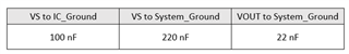
My customer have a question about applying PWM signal to EN pin. Please check the schematic first.

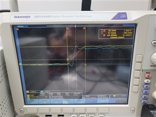
- They checked 6A current output on VOUT[X] pin if EN pin is 5V constant.

- But if they apply PWM signal to EN pin, they have some troubles.

1. What is maximum current output of VOUT[x] pin if 200Hz PWM signal is applied to EN pin? (Maximum input current of VS[x] is 10A.)

2. What is maximum current output of VOUT[x] pin if 960Hz PWM signal is applied to EN pin? (Maximum input current of VS[x] is 10A.)

3. What is maximum and minimum value of PWN frequency which can apply to EN pin?

And, Could cyou check the same question in case of using TPS1HTC30AQPWPRQ1?

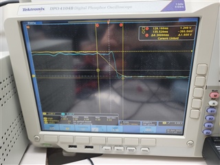
They checked 8A current output on VOUT[X] pin if EN pin is 5V constant.

- But if they apply PWM signal to EN pin, they have some troubles.

1. What is maximum current output of VOUT[x] pin if 200Hz PWM signal is applied to EN pin? (Maximum input current of VS[x] is 10A.)

2. What is maximum current output of VOUT[x] pin if 960Hz PWM signal is applied to EN pin? (Maximum input current of VS[x] is 10A.)

3. What is maximum and minimum value of PWN frequency which can apply to EN pin?

Please check these issues. Thanks.

Best regards,

Chase

  • Hi Chase,

    I am working on this, I will get back to you tomorrow.

    Best Regards,

    Rishika Patel 

  • Hi Chase,

    Sorry for the delay.

    Schematic review for both devices:

    -For 5V MCUs, 10k is recommended for the protection resistors. 

    -What is the purpose of the capacitor on the latch pin?

    -RSNS is quite large. We typically recommend calculating it based on the RSNS equation given in the datasheet and such that it does not cause a false fault condition. 

    -The ground network RGND and DGND should be connected in parallel; it seems two different ground points are used. 

    -The following set of capacitor connections is recommended for optimal EMI performance:

    For the TPS1HTC30-Q1, the max PWM frequency is 750 Hz.

    For the TPS1HTC100-Q1, the max PWM frequency is ~2 kHz at a 50% duty cycle. Please make sure that the device has enough time to fully turn on and turn off while considering delay times; thermal dissipation due to factors like board layout and switching loss also play a role so just make sure the device does not go into thermal shutdown. 

    For the maximum current output - ideally the current will be either high when EN is high or low when EN is low (assuming the device has enough time to fully turn on and off); when EN is high, the current VS is supplying (the current draw is based on the load) is about how much current is flowing through the switch to the load. 

    Best Regards,

    Rishika Patel 

  • Dear Rishika,

    Thank you for your support.

    I did some tests with my customer. It seems that TPS1HTC30-Q1 and TPS1HTC100-Q1 allow PWM signal to EN pin.

    First could you check that I can apply PWM signal to EN pin?

    And please also check the test results below.

    1. TPS1HTC30AQPWPRQ1 (VS[x]=12V, EN=5V, loader is connected to VOUT[x] and set to 3A.)

    1) PWM 200Hz to EN pin

    - duty 100% : Output 3A, 11.06V

    - duty 90% : Output 2.77A, 9.8V

    - duty 80% : Output 2.45A, 8.6V

    - duty 70% : Output 2.17A, 7.6V

    - duty 60% : Output 1.88A, 6.5V

    - duty 50% : Output 1.58A, 5.4V

    2) PWM 400Hz to EN pin

    - duty 100% : Output 3A, 10.8V

    - duty 90% : Output 2.84A, 9V

    - duty 80% : Output 2.5A, 7.2V

    - duty 70% : Output 1.5A, 2.0V

    - duty 60% : Output 0.95A, 1.4V

    - duty 50% : Output 0.9A, 1.4V

    2. TPS1HTC100AQPWPRQ1 (VS[x]=12V, EN=5V, loader is connected to VOUT[x] and set to 3A.)

    1) PWM 200Hz to EN pin

    - duty 100% : Output 3A, 10.9V

    - duty 90% : Output 2.73A, 9.5V

    - duty 80% : Output 2.47A, 8.5V

    - duty 70% : Output 2.17A, 7.4V

    - duty 60% : Output 1.88A, 6.3V

    - duty 50% : Output 1.59A, 5.2V

    2) PWM 400Hz to EN pin

    - duty 100% : Output 3A, 10.9V

    - duty 90% : Output 2.86A, 9.5V

    - duty 80% : Output 2.5A, 8.1V

    - duty 70% : Output 2.21A, 7.1V

    - duty 60% : Output 1.95A, 6.1V

    - duty 50% : Output 1.64A, 4.9V

    3) PWM 600Hz to EN pin

    - duty 100% : Output 3A, 10.9V

    - duty 90% : Output 2.9A, 9.1V

    - duty 80% : Output 2.56A, 7.9V

    - duty 70% : Output 2.25A, 6.7V

    - duty 60% : Output 1.94A, 5.6V

    - duty 50% : Output 1.62A, 4.5V

    Please check and give me your opinion.

    (RGND and DGND are tied togeter in test PCB. and RSNS is 1kohm now. rest of the suggestions will tested by customer.)

    Best regards,

    Chase

  • Hi Chase,

    Yes, you can PWM using the EN pin. Please refer to the following E2E on how to calculate if the frequency/duty cycle gives the device enough time to turn on and turn off.

    (+) TPS1HTC100-Q1: Max PWM support - Power management forum - Power management - TI E2E support forums

    I will provide more feedback on the data tomorrow. 

    Thanks,

    Rishika Patel 

  • Dear Rishika,

    Thank you for your support.

    I measured EN and OUT in case of rising and falling of EN pin, but the time gap of EN and OUT is very short.

    So I think it is not a problem of turn on and turn off especially this low frequency and duty cycle.

    (EN pin is rising, yellow is EN pin, blue is output.)

    (EN pin is falling, yellow is EN pin, blue is output.)

    And one more request, please also do some tests on your site using EVM or something if you can, using the conditions above.

    Or, Can you guide me about test methods?

    (for example, do not use electric loader, use other equipment instead, etc...)

    Best regards,

    Chase

  • Hi Chase,

    The waveforms look fine for turn on and turn off, but it does seem like there is slight oscillation on the curves. Although doing an experiment can provide a good idea of the typical turn on or turn off time, it is better to calculate the worst-case scenario including the maximum delay times.

    For resistive loads, we recommend using purely resistive loads like a power resistor/box. We do not recommend using e-loads in constant current mode because they cause issues with our high-sides switches since it is trying to draw a pre-set current at all times (detailed explanation at the link below). If an e-load needs to be used, please be sure to use it in constant resistance mode. 

    (+) [FAQ] Why does my e-load cause my high side switch to shut down? - Power management forum - Power management - TI E2E support forums

    For the data you provided before - did you calculate this or did you do the experiment and see these values? PWMing does not change the output current or voltage unless you do not give the device enough time to fully turn on or turn off. So, in an ideal situation when the device is on, the output voltage will be the same as the input voltage and the current will be as expected based on the load. The data you provided does not follow this concept. 

    Thanks,

    Rishika Patel 

  • Dear Rishika,

    Thank you for your support.

    1) I actually did the test and saw these values. As you can see, output voltage is going down as duty cycle is going down. And I suspect that it is because high side switch cannot bear desired output current so output voltage drop could be happen. <- Am I right?

    2) You recommend to use resistive load instead of e-loads. Does resistive load look like below? (I did not use it before, It is just a resistor with very large power capacity.)

    3) You said that it is better to use constant resistance mode instead of constant current mode, if I use e-loads. I will check it with my customer but I am not sure it has constant resistance mode in their equipment..

    4) Do you have any test results which apply PWM signal to EN pin? then my customer can refer the results for debugging.

    Best regards,

    Chase

  • Hi Chase,

    1. VS = 12V, EN = 5V, and I = 3A (TPS1HTC30-Q1 can handle 6A nominally and TPS1HTC100-Q1 can handle 4A) are all within recommended device operating conditions so it should not be an issue. 

    2. Yes, it can look like that. A power resistor box can also be used; with this, you can adjust the resistance. Please keep the power ratings in mind.

    3. It is possible that this behavior is due to the e-load in CC mode so in order to get an accurate representation of how the device is functioning and reacting, the e-load needs to be in CR mode. 

    4. You can refer to the following app note, specifically Figure 3-1, to see how the waveform should look during normal operation and what it can look like when switching too fast. It is not for this specific device but it is the same concept. 

    Driving PWM Loads with TI High-Side Switches

    Thanks,

    Rishika Patel