This thread has been locked.

If you have a related question, please click the "Ask a related question" button in the top right corner. The newly created question will be automatically linked to this question.

LM5146: oscillations, stability problems

Part Number: LM5146

Tool/software:

Hi.
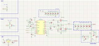
I am using a dc/dc converter on an LM5146 chip.
Uin = 20-30v. Uout = 5v. Freq = 200kHz.
Iout = 14A.


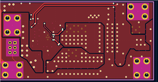
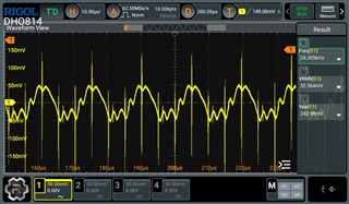
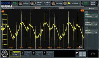
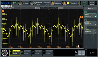
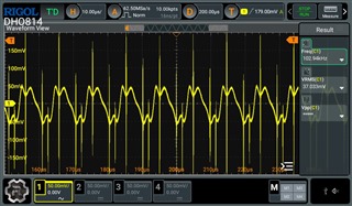
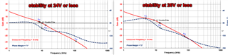
I have configured feedback compensation but it does not work at Uin above 24-24.1v.
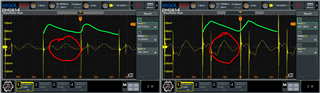
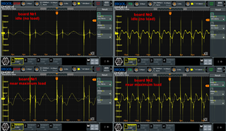
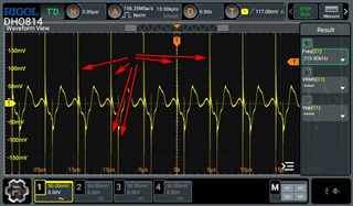
When Uin > 24.1v at high currents (Iout) oscillations start. The higher the voltage, the lower the current at which stability is lost.
Bode diagram shows that everything is fine, but it is not.
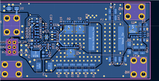
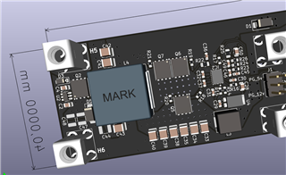
Maybe there are parasitic components on the board. But I don't know how to find them.


I also want to say that the same boards work in 50v->24v and 30v->12v mode. There are no problems with them. But the boards are the same.
I think that the problem occurs when there is a big difference between Uin and Uout. When the reduction is 5 times or more.


I tried reducing cross frequensy below 10kHz, but it doesn't help. Only the oscillation period changes.
I will provide you with quickstart calculator, waveforms, schematic, and board design.

I will be very happy if you can help me.

 LM5146-Q1 Quickstart 5v_14a.xlsm

  • Hello,

    Looks unstable - please check stability with the quickstart calculator and ensure that ceramic Cout is correctly derated. Max crossover is 15% of Fsw.

    --

    Tim

  • 1. I checked the Cout capacity reduction. The quick start calculator shows that the system should be stable. Crossover was dropping even below 5%. It did not help.


    2. Experimentally I was able to stabilize it to 26 volts. (previously it was up to 24). As I understand on the left diagram the system should be more stable? But in practice the right diagram works better. I don't understand why this happens.


    3. When the output voltage is stable, instead of a flat line (green line) I observe some resonance when the upper key is closed (yellow circle). What can it be and how to remove it?

  • The crossover seems very close to the LC tank frequency. Are you sure the LC damping is correctly modeled? It seems very overdamped in the bode plots above

    Send on the quickstart file for review.

  • Here's the quick start file:

    LM5146-Q1 Quickstart 5v_14a_170625_1.xlsm

    With these parameters, I was able to stabilize the output voltage with an input voltage of 29V or lower. However, when I soldered the same compensation components to other boards the fluctuations started already at 24-26 volts.

    I also noticed that the oscilloscope of ripple is different on the boards. Of the five boards, two have ripple #1 and the rest have ripple #2. At the same time #2 has a larger amplitude of ripple than #1.

    Can you also tell me how I can remove the high frequency interference?

    Their frequency is about 30-50MHz. There are already ceramic capacitors on the output. What can I do?

  • Okay, thanks for the file. I'll take a look and get back to you shortly.