This thread has been locked.

If you have a related question, please click the "Ask a related question" button in the top right corner. The newly created question will be automatically linked to this question.

UCC28951: Queries

Part Number: UCC28951

Tool/software:

Hello Mike,

1. The Excelsheet calculator provided mentions Dmax as 0.66 ?  datasheet says it can go upto 95%. Can we manually Adjust Duty cycle as per our requirement ?

2. The excel tool considers 20% ripple of output inductor current while calculating Lmag, can i consider 40% ripple current ? what are the implications overall on the converter operation? OTS parts are readily available if i consider 40% ripple.

3.can i consider 10% ripple current ? what are the implications overall on the converter operation? OTS parts are readily available if i consider 10% ripple ?

4. additionally, the excel tool calculates Lmag value considering Typical Voltage, not minimum Voltage.  i think there's a correction to be made in the calculation sheet.

5.


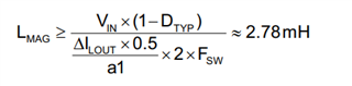
As per your suggestion, I'm substituting Dmax in place of Dtyp, Vin min, in place of Vin in the above formulae to calculate Magnetizing Inductance, is that correct ?

6. 

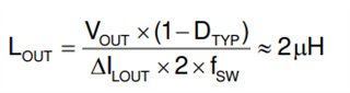
I'm substituting Dmax in place of Dtyp, in the above formulae to calculate output Inductance value, is that correct ?

7. sharing Two excel sheets, Let me know if any corrections are required. Please review the files. Especially Loop response values for 24V variant.  

2376.SLUC222E - 63277 R05_12V.xlsx

SLUC222E - 63277 R05_24V.xlsx

  • Hello,

     1: The excel tool is setting the maximum duty cycle to calculate the transformer turns ratio.  If does not limit the max duty cycle to 66%.  The device can still achieve a max duty cycle typically of 95%.

    2:You can design your output inductor for 40% ripple current. This will cause design to operate at critical conduction at 20% load.  This means that you need to turn your SRs off at higher load than if you designed for 20% ripple.

    3:If you want to size your output inductor ripple current for 10% that is O.K. You actually will run at critical conduction at 5% load.

    4 and 5:  I reviewed the application note on this and the idea is to size the magnetizing inductance current to less than 50% the reflected output current.  This is so the magnetizing current does not end up being controlled instead of the output inductor current.  If you make Lmag too small it could cause the design to misbehave.  I think you are correct that you could have used maximum duty cycle and minimum input voltage to calculate Lmag.  You can do this by hand and enter the used value in the excel tool.

    6:  That is O.K.

    1. The excel tool is given as tool to help you review your design. It also goes along with application note slua560 which can be found at the following link.  It is recommended that use values that are within +/- 5% of the recommended values.

    https://www.ti.com/lit/pdf/slua560


    Regards,