This thread has been locked.

If you have a related question, please click the "Ask a related question" button in the top right corner. The newly created question will be automatically linked to this question.

BQ79616: UART issue with STM32F105VCT6

Part Number: BQ79616

Tool/software:

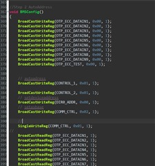
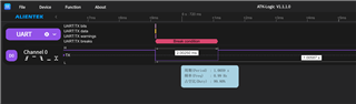
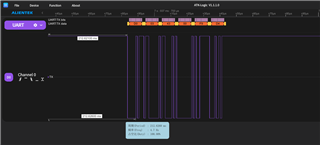
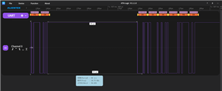
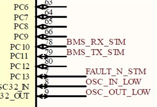
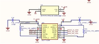
Hi, I am designing a bms using BQ79616 chips with STM32F105VCT6, the chip is successfully wake up but stm32 cannot receive anything, we use baud rate of 1mbps. Can anyone help on this?

  • Chan,

    Do you perform auto-addressing before attempting to read from the device? A top of stack must be created before reads are possible.

    Regards,

    Bo

  • Hi Benjamin,

    Thanks for replying.


    Provided is the snippet of the code in stm32 for auto-addressing, note that we are using stm32f105vct6 directly connected to the bq79616 (we are not using bq79600 as the communication bridge),we only use one bq79616 for 14 cells monitoring and do not have any stacked device, we are using a single device and we set it as the base device.


    These are the picture of the tx signal from stm32 captured by logic analyzer, the first one refer to the wake up signal and the second and third refer to the autoadressing. The bq79616 wake up once it received the wake up signal, CVDD is 5V, DVDD is 1.8V and AVDD is 5V as well, but the TX of bq79616 is not responding anything to the stm32.


    Provided above is the stm32f105vct6 connection with the bq79616, we use a logic shifter in between them.


    for testing purposes, we powered bq79616 with external power supply of 40V, touching BAT and CELL0 accordingly. (reference to TI bq79616EVM schematics )
    TuesdayGreen.zipBMS0.pdf
    this is the complete code for wake up and auto-addressing and the complete schematics of our self-developed board

    Regards,
    Chan

  • Currently I am attempting to perform OTP programming via UART using an STM32 microcontroller.

    I have followed the recommended procedure, including the correct unlock sequence and setting the OTP_PROG_CTRL register. However, I noticed that the LDOIN voltage remains at 6V during the entire process, which suggests that OTP programming may not have actually initiated. According to the datasheet, I understand that LDOIN should rise to 8V during a valid OTP programming operation.

    To debug this, I verified the UART communication from the STM32 side using a logic analyzer, and I can confirm that the unlock and OTP programming commands are being transmitted correctly with the proper CRC. However, I am unsure whether the BQ79616 is actually receiving or accepting the commands, as I do not receive any UART responses from the device (even before the OTP step in some cases).

    Could you please advise on possible reasons why the LDOIN voltage would remain at 6V and whether there are additional conditions or indicators I should check to confirm that the OTP sequence was accepted by the BMS device?

  • Chan,

    There are a few reasons your communication could be failing. I will present them here in no particular order:

    1) Your level shifter or isolation scheme is not correctly transmitting the signals. Check that the signal entering the pins of the IC is within acceptable levels for a long enough period to be recognized as communication.

    2) I see your auto-addressing scheme is completely incorrect. The biggest issue is that sending CONTROL1[ADDR_WR] =1 only allows the next command to edit the DIR0/1_ADDR register. You are enabling TSREF between the setting of ADDR_WR and the setting of DIR0_ADDR. Wait until after auto-addressing to make any configuration changes to such registers. Additionally, you are writing to too many registers as part of the Dummy Write process. You only need to write to ECC_DATA1 to ECC_DATA8. You are writing to ECC_DATA9 and ECC_TEST. 

    As for OTP programming, I would not recommend attempting it until you resolve your communication issues. It is entirely possible that you have already initiated OTP programming in this device before without realizing it and now it can never be programmed again.

    Regards,

    Bo

  • Hi Benjamin,

    STM_TX.zip
    FridayYellow.zip
    output. I have removed all irrelevant sections and ensured that the procedure strictly follows the required steps. However, the RX line still does not receive any input. I would appreciate your assistance in identifying the root cause of this issue. All power rails are working according to the datasheet: CVDD is 5V, DVDD is 1.8V, and AVDD is 5V. The auto-addressing procedure has also been followed correctly. What could be the possible causes of this problem?

    Regards,
    Chan