Tool/software:
Hi Team,
Please review the attached schematics for Vin = 5V, Vout = 1.2V. Also attached is the component calculator sheet.
/cfs-file/__key/communityserver-discussions-components-files/196/TPSM8287A15BAHRDWR_5F00_1V2.pdf
Thanks
This thread has been locked.
If you have a related question, please click the "Ask a related question" button in the top right corner. The newly created question will be automatically linked to this question.
Tool/software:
Hi Team,
Please review the attached schematics for Vin = 5V, Vout = 1.2V. Also attached is the component calculator sheet.
/cfs-file/__key/communityserver-discussions-components-files/196/TPSM8287A15BAHRDWR_5F00_1V2.pdf
Thanks
Hi,
Thanks for using the calculator!
Your chosen Rcomp1 value is much larger than the calculator suggests. Also, the output capacitance entered is the nominal value, not the effective value. Why is that?
Can you send the part numbers for the 10uF Cin and the 100uF Cout?
Also, the EN pin needs at least a 15k resistor in series with it.
Thanks,
Chris
Hi Chris,
1. For cross-verification, I calculated the Rcomp1 and output capacitance value using the formula in datasheet and used it in design.
2. According to calculator Rcomp1 calculated is 2.89K, will it be good if I use 3K? .
3. As for output capacitance for 3K Rcomp1, i will use 3x 100uF, 1x 47uF for a total of 347uF capacitance, will that be good?
4. Based on 3K Rcomp1 and 347uF output capacitance, will 1.2nF Ccomp1 be good?
5. 10uF - GRM188R61E106KA73D, 100uF - GRM21BR60J107ME15L, 47uF - C3216X5R1E476M160AC
6. Is it fine to leave SCL, SDA and SYNC_OUT pins floating?
7. Is it necessary to provide pull-up for PG pin or can I leave it floating?
Thanks
Hi,
Thank you for explaining.
Those input caps do not provide the required 5uF effective Cin, under DC and AC bias voltage. Can you use this cap instead? GRM188C81A226ME01D

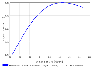
Depending on your temperature range, those 100uF Couts have between 53 and 63 uF of effective Cout. This is the value that you need to use in the spreadsheet, as it is how much capacitance is actually present in the circuit.

From your spreadsheet, I picked a 3.01k Rcomp1 resistor. Then, the 8x 100uF caps give sufficient capacitance. Ccomp1 is then about 1500pF.
Yes, you can leave PG and SYNC_OUT floating. You should connect SDA and SCL to GND, if not using them.
Chris
Hi Chris,
1. According to calculator Rcomp1 calculated is 2.89K, will it be good if I use 3K? .
2. As for output capacitance for 3K Rcomp1, i will use 3x 100uF, 1x 47uF for a total of 347uF capacitance, will that be good?
3. Based on 3K Rcomp1 and 347uF output capacitance, will 1.2nF Ccomp1 be good?
4. 100uF - GRM21BR60J107ME15L, 47uF - C3216X5R1E476M160AC
5. Instead of using 2x 10uF, will using 2x 22uF (GRM188C81A226ME01D) suffice for Cin?
Also find the component calculator attached.
Thanks
Hi,
1. Yes, 3k is fine or 3.01k is a standard resistor value.
2. I don't think this is enough capacitance, since the effective capacitance will be less than the nominal value. You need to enter the effective capacitance in cell C26.
3. No, I think this is too high. You need to enter the actual, effective capacitance first.
4. Ok.
5. Yes, those give enough effective capacitance for Cin.
Chris
Hi Chris,
1. I will provide 5x 100uF and 2x 47uF for Cout, is that good?
2. Considering above point will the selected Ccomp1 be good?
Thanks
Thank you for confirming.
1. Yes, that looks like enough Cout.
2. Yes, 1.2nF looks like a good value.
Chris