This thread has been locked.

If you have a related question, please click the "Ask a related question" button in the top right corner. The newly created question will be automatically linked to this question.

LMZ14203: Maximum Output Range.

Part Number: LMZ14203

Tool/software:

Hello gracious members,

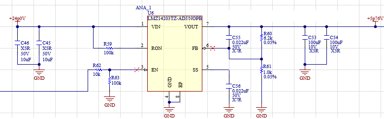
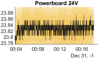
I have the above mentioned LMZ part that I am currently using at 24V input and 5.76V output, and it runs stable. I am looking to increase my output to 6V due to observed supply droop over long periods of time. In testing I see that the output is no longer stable in all cases, and with a dynamic load can go out of regulation and rail (in some cases to a value that persists on a power cycle).

In other threads I have seen comments relevant to output range ratings, specifically here, and here. The first states that outside of the minimum rating for the 'H' part, the circuit will need to be tested for stability. The second states that the maximum recommendation for the normal part is 5V. 

Put simply, I am seeking confirmation that the maximum ratings are set as bounds for stability for each separate part? Is the 'recommended' upper limit for stable operation of the LMZ14203 part 5V or 6V? Secondarily, the operation of the 'Output Overvoltage Protection' in this state seems irrelevant since I have observed lower than normal FB voltage, rather than higher, which wouldn't trip the protection?

Thank you for your time,

Cuyler

  • Apologies for typo

    1. The device is rated for output voltage upto 6V

    Please share you schematic.

    What is "supply droop"? It could be issue with input power supply that you are using or may be the current limit is hitting for the supply. Recommend to increase the current limit for supply can check.

    Please share schematic and waveforms of VIN, Vout, Vfb.

    2. I have observed lower than normal FB voltage, rather than higher, which would trip the protection

    Do you have wwaveforms?

    Regards

    Arpita

  • Arpita, 

    Schematic excerpt below

    Please note EN is connected to a supervisor chip, which currently is only being used to monitor voltages, and will not disable the chip.

    I double checked the current draw of the load we are driving, and it does not require 3A, rather a number much closer to 1A (measured as .938A). The supply I am using is rated for 4.5A at 24V. 

    The 'droop' I am referring to is an observed loss in the supply voltage over many operating hours. Over time this is causing issues downstream. Historically this issue has been resolved by reducing the resistance in our b2b connectors, which indicates to me that I am entirely too sensitive to voltage droop with increased load (Seemingly caused by corrosion over time). Hence, motivation to be increasing Vout.

    For Vfb, I typo'ed at the end of my statement and said 'would trip the protection' rather than 'wouldn't' which was my intended indication. I've edited my post to reflect that. The chip is not going into overvoltage protection, because the Vfb is not going out of the acceptable range in the unstable state. 

    I'll attempt to replicate the unstable state I observed and capture waveforms. At this time I only have a Vout waveform, and I don't see anything of note in that data, and it doesn't entirely encapsulate the issue I was seeing. The unit I was able to produce the behavior on has since been repaired, and I am having trouble recreating the issue as it appeared on a different system. 

  • Hi Cuyler,

    I could not open/see the schematic. Could you please re-attach it? 

    Regards

    Arpita

  • Hi Cuyler,

    How is the input supply connected to the Vin pin of the IC? Is it through a long cable/ wire? Supply voltage droop after few hours looks like an issue from input power supply side rather than the IC performance. What kind of supply are you using? Kindly share waveforms

    Regards

    Arpita

  • Hi Cuyler,

    Closing due to inactivity. Please feel free to reopen if you have any update.

    Regards

    Arpita

  • Not through a cable. There is input voltage treatment with a power filter and some input capacitors. I have a trace of the input voltage attached. It's extremely steady over time and I do not think it is causing any issue. 

    The supply is a 120V inverter capable of delivering 6A. 

  • I have solved the instability issue I observed and identified the root cause as a capacitor which was cracked from rework. C55 was causing an intermittent short across Vout to FB.

    I do still have the question I asked in my original post. Are the maximum ratings are set as bounds for stability for each separate part? Is the 'recommended' upper limit for stable operation of the LMZ14203 part 5V or 6V?

  • As stated earlier, The maximum possible Vout for the device lmz14203 is 6V.

    Regards

    Arpita