This thread has been locked.

If you have a related question, please click the "Ask a related question" button in the top right corner. The newly created question will be automatically linked to this question.

BQ25756: Mosfet short when charging

Part Number: BQ25756
Other Parts Discussed in Thread: EV2400

Tool/software:

Dear Expert

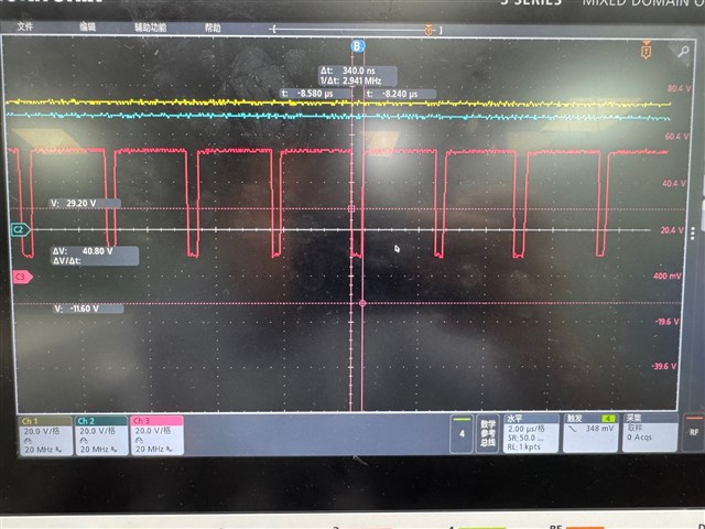
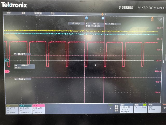
Our test condition is 51Vin & 54Vout & 1.2A .Output connected the electrical laod.

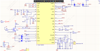
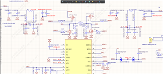
But we found mosfet is easy to short ,and the temperature of MOSFET was measured using an infrared instrument and reached 100 degrees Celsius. Bur we caulate these output condition seems not caught these too high temperature.Below is our sch ,could u hlep to give me some advice.

Below is mosfet datasheet

XPT1H13A4,NMOS 100V 10mr TO252,1200pf.pdf

  • Hi,

    Looking at the schematic, the BTST diode selections does not look like a Schottky diode. Can you confirm this? This diode needs to be a Schottky diode.

    What does the SW1 and SW2 waveform look like?

    Best,
    Michael

  • Hi Michael,

    Thanks for your reply! I'm the FAE covering this customer. Customer changed the Schottky diode on our EVM board on their own board. But the issue still exists. I caught the SW waveform. It looks normal. I also tested the Gate waveform but haven't caught it then the Mos burned. The only difference between our mos and customer's is that customer's MOSFET is 10mR Rds on. Do you think this might be an issue? 

    BR,

    Jiaqi

  • Hi Jiaqi,

    Thanks for working with this. I do not think that the 10 mOhm RDSon will be an issue that causes a large temperature at 1.2 A. Which MOSFET is burning out?

    Best,
    Michael

  • Hi Michael,

    The device is working in Boost mode to convert 48V to 54V battery. Usually all the four Mosfets would be burned out. 

    Br,

    Jiaqi

  • Hi Jiaqi,

    I have a couple of tests I would like to try:

    • What does the input and output current waveform look like?
    • What does the HIDRV1/HIDRV2 and LODRV1/LODRV2 waveforms look like? I would like to see these on the same plot if possible.
    • Can you send me the register readings of the device during this operation?
    • What happens when you set EN_CONV_FAST_TRANSIENT = 0 with I2C? This has helped with similar situations.
    • Does changing the inductor on the board to a different inductor or the inductor from the EVM change the behavior?

    Best,
    Michael

  • Hi Jiaqi,

    Do we have any updates with the MOSFET short?

    Best,
    Michael

  • Hi Michael,

    I asked customer to send me a PCB board for test. I tried to test the waveform of gate driver pin. It looks good but the MOSFET short before I took the screen shot. I will do some test in TI lab. I also found another issue might be an issue. Customer are using 2 power supply in series as the 48V power supply. One is 36V and another is 12V. It's hard to turn off the power supply together. I will use a single power supply for test.

    BR,

    Jiaqi

  • Hi Michael,

    Another two concerns from my side. One is customer is using a Hand-wound inductor. Does this make sense? Another is I found the device works normal with no IIC control but only the output voltage is not stable. But if my connect the EV2400 on customer's board. The device may has some possibility of damage. I only conect SDA/SCL and GND line. 

    BR,

    Jiaqi

  • Hi Jiaqi,

    Will the hand-wound inductor be used in the final design? Does it meet the minimum/maximum inductance and DCR requirements? Do we know the parameters of the inductor? If we don't know these parameters, see if the board behavior improves using the inductor from the EVM. Additionally, since this is a hand wound inductor, can we measure the inductor current waveform? This should provide some useful information.

    What do you mean by the output voltage is not stable? Please provide a waveform. What are you using as the output load?

    What are the IIC settings being used for the control? Does the MOSFET short after writing IIC commands or after plugging in EV2400?

    Best regards,
    Michael

  • Hi Michael,

    I still need some time to test the waveform as customer has run out of the samples. I applied for some new. The output voltage will range from 53V to 54V and will be stable if I disable the watchdog and enable CHG. And sometime the MOSFET will be damaged after writing IIC commands. 

    BR,

    Jiaqi

  • Hi Jiaqi,

    Thanks for the update. Let me know once the new samples are in.

    Best regards,
    Michael