This thread has been locked.

If you have a related question, please click the "Ask a related question" button in the top right corner. The newly created question will be automatically linked to this question.

TPS2116: Reverse leakage current after some time

Part Number: TPS2116

Tool/software:

Hello,

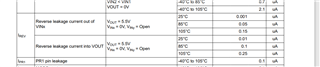
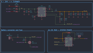
on a recent design using the TPS2116, we experience a unusual issue. IN1 is connected to the output of a buck converter. The PR1 pin is connected to the power good output of the buck regulator. IN2 is connected to a primary lithium battery. The device and circuit start working perfectly on a fresh board (no reverse leakage, no significant quiescent current etc.) but after some time (some after weeks some after days) a significant current starts going from the battery (IN2) to the output of the buck converter (IN1). This was determined by isolating the circuits so only the TPS2116 is the possible culprit. The current on some devices is in the tens and some are in the hundreds of uA which drains the battery prematurely. Both the battery and the buck regulator operate at 3.6V. The battery serves as a backup source when no input DC voltage is available.

Any thoughts on how to mitigate this issue and what could cause it? Both inputs are protected and reverse voltage protected so no possible way for that to cause any damage, especially in a controlled environment and after some undefined time.

Thanks in advance.

  • Hi ,

    What is the exact test case in which you see leakage from vin2 to vin1

    Regards 

    Kunal Goel

  • Hi Kunal,

    The output of the mux is disconnected (trace is cut). The buck regulator that goes to VIN1 is not powered, his power good output (which is connected to PR1) is verified low and as such VIN2 should provide power to the output which it does, but I also measure some voltage (couple of volts, depends on board) on the VIN1 port which should not be the case. With that I get a significant battery leakage current. On a fresh board, it works just fine as it should, but on these "faulty" ones I measure in the hundreds of uA which is not acceptable. 

    On another post about this IC, there is mention to decrease the input impedance, so the input isn't "floating", I tried adding a 1k resistor on the buck output, but I still get some leakage. I'm also worried that the buck might try charging the non-rechargeable lithium battery and cause significant damage.  

  • Hi Krunoslav,

    We have some reverse leakage current as per datasheet. 

    Regards

    Kunal Goel

  • I'm well aware that some leakage current is expected but I measure >100uA not 0.1uA. 

  • Thanks. Please share schematic for review. 

    Regards

    Kunal Goel

  • Please see the attached schematic. R80 and Q9 are removed so they 100% don't cause any issues. 

  • Hi,

    Please let me check and get back. 

    Regards 

    Kunal Goel

  • Hi Krunoslav,

    Were you able to figure out the issue?

    I'm working on a low power design and planned on using the same IC in a similar configuration (VIN1 is USB + LDO powered and VIN2 is battery powered), so I'm curious to know if there indeed is an issue with the MUX. 

    Also, when you mentioned isolating the circuits, are R80 and Q9 still present, or did you remove them as well? Just wondering if they, and any associated measurement / control circuitry, could be loading the battery in some situations. You mention that you don't have this leakage issue initially, and so perhaps this point is moot, but just putting it out there. 

    All the best!

  • No, the issue is still not resolved. Current plan, if TI doesn't have any ideas, is to add a series diode on VIN1 and increase the buck voltage to compensate. This should prevent leakage from VIN2 to VIN1 should it happen again. I'm not too worried about VIN1 leaking into VIN2 as there isn't really any significant leakage when both ports are powered. This issue only happens, at least in my case, when VIN1 isn't powered. I did try to add a 1k resistor to GND on VIN1 to act as a strong pull-down, but my guess is that the IC's get somehow get damaged internally. 

    Yes, R80 and Q9 are removed and the leakage still exists. Even with them fitted they don't cause the leakage, but for the sake of faster troubleshooting I removed them. What you see on the schematic above, is all there is for the battery circuit.

  • Hi Krunoslav,

    Sorry for delay. My only suggestion is to submit device for failure analysis. We have not seen such issue before. 

    www.ti.com/.../createReturn.tsp

    Also agree with your idea to use diodes. 

    Regards

    Kunal Goel