This thread has been locked.

If you have a related question, please click the "Ask a related question" button in the top right corner. The newly created question will be automatically linked to this question.

HD3SS3220: Only enumerates in SS mode when the attached cable is in one orientation, but HS in the other

Part Number: HD3SS3220

Tool/software:

I have some pretty weird behavior going on with this part that I'm trying to get to the bottom of. The device is supposed to be operating in as a DFP. When the device is powered on with a USB cable attached, it is always able to communicate in SS mode regardless of orienation of the cable. However, if the cable is unplugged and plugged back in, it will only operate in SS mode when the cable is in one orientation, but not the other. The same behavior occurs if the device is powered up with no USB cables attached. Tring to get to the bottom of it, I've checked the DIR pin, and it looks like the DIR pin is never being pulled low unless the cable is plugged in at start up and not removed. I also read the Connection Status and Control Register, and saw the following:

Device powered up with cable connected: 0x50 or 0x70 depending on direction

Device powered up with cable attached and then removed: 0x30 in all cases

Device powered up with no cable attached: 0x20

Device powered up with no cable attached and then a cable is attached: 0x20 in all cases

I assume this is an issue with the CC pins, since the CC state is only being set correctly on power on, and not while running, but the CC_EN_L signal is pulled low, as is the MUX_EN_L.

Any ideas?

Thanks,

Matt

  • I forgot to mention that the cable has been tested on other systems and works there, so not a cable issue. It is a USB C to USB B Micro 3.0 cable with no active components in the cable.

  • Hi Matt,

    How is the ID pin being used? Is it attached to an SOC or a VBUS switch and controlling when VBUS is sent? Or is it left unattached?

    Could you the the schematic for your HD3SS3220?

    Thanks,

    Ryan

  • It is unattached. There is a pull up on it, so I can read it, but it isn't being acted on.

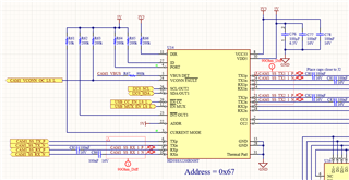
    Schematic is here: 

    The upstream signals are coming from a USB hub, which is responsible for controlling VBUS. The CC and MUX EN lines can be controlled by a processor, but aren't being used and remain low at all times currently. I2C pull ups are 4.7k to 3V3, and there are 2 of these plus an EEPROM and 2 DAC's on that bus.

  • Hi Matt,

    The ID pin on the HD3SS3220 needs to be used with a GPIO on the SOC or the enable pin of a VBUS switch to control when VBUS is sent through the USB-C port. VBUS being enabled is part of the CC negotiation when acting as a DFP, and should only be enabled when the ID pin goes low. If VBUS is not controlled via the ID pin, then functionality will suffer, like in this case where a USB3 connection only happens in one flip orientation but not the other. I would recommend properly controlling VBUS via the ID pin.

    Another thing I noticed is these caps on the RX lanes connecting to the hub. These caps should either be 330nF, or there should be no caps at all. Using caps of 100nF will result in the capacitance on the line being below what is accepted in the USB3 spec, assuming the device side has their TX lines properly coupled.

    Thanks,

    Ryan

  • I will test out controlling the VBUS_EN with the ID pin on the mux and see how that works and get back to you. If that works, I will likely just OR the signal from the hub and signal from the mux together in the next spin, so either can disable the VBUS.

    Regarding the caps, these are the only caps on those lines. Though this brings up another question. Based on my reading of the datasheet, it looks like TX on this part is referring to TX for the USB bus as a whole, and would then be connected to TX coming out of the Hub. My understanding was that the TX signal coming into the mux is passed through to either TX1 or TX2. So I have 2 caps on TX coming from the hub and 2 caps on RX coming back from the MUX. I figured this would make sense, because I can sometimes enumerate a device as super speed, which wouldn't be possible if they were flipped. Is this not the case?

  • Hi Matt,

    In general, all USB3 lanes are required to have the lines coupled to be within 75nF to 265nF of capacitance to meet the USB3 spec.

    The TX pins on this mux will route TXp/n from the hub to TX1/2 p/n pin on the type-C connector, and both those TX lanes should be coupled per the USB3 spec, which in this case is typically 100nF or 220nF depending on the designers preference. It looks like right now you have 100nF caps on the TX1/2 side of the mux so as long as there aren't more caps on the hub side of the mux, there should be no issues there.

    For the RX pins, you have to route these lanes under the assumption that the connected device has it's TX lanes correctly coupled, I.E 100nF or 220nF caps on the TX pins on the device side before it moves through the USB-C cable. So assuming those are routed correctly, if you were to use 100nF caps on the RX lanes, it would be in series with either 100nF or 220nF of capacitance. At 100nF, it would put the line capacitance at 50nF and out of spec. At 220nF, the line would go down to 68nF of capacitance, still out of spec.

    As such, for the RX lanes, we typically recommend either no caps, which would cause the lane to rely on the RX from the connector being properly coupled, or 330nF caps, which can help support a variety of capacitance and ensure it is still within the limits of the USB3 spec. For example, 330nF RX caps with 220nF on the RX lane would result in a line capacitance of 132nF, and 330nF caps with 100nF on the RX line would result in 76nF of capacitance, still within the spec.

    If the capacitance on the line is out of spec, it could result in impaired functionality on the USB3 lines. As long as you have an overall capacitance of 100nF on the TX lane between the hub and the connector and no caps or 330nF caps on the RX lane between the connector and the hub, it should be okay.

    Thanks,

    Ryan

  • Ok, I think I understand. Does this mean that as long as the connector side of the Mux has the proper caps, I don't need any caps between the hub and the mux?

  • Hi Matt,

    Yes, correct. You can place the caps on either the connector side of the hub side, it doesn't have to be exclusively one side, as long as the overall capacitance on the lines is within what is spec'd in the USB3 spec.

    Thanks,

    Ryan

  • Hi Matt,

    I am marking this thread as resolved due to inactivity. If you have any questions or need more assistance, feel free to reply here.

    Thanks,

    Ryan