


Other Parts Discussed in Thread: TPS1211-Q1, , LM74800-Q1
Tool/software:
Hello,
according datasheet,
Minimum required capacitance for charge pump VCAP is based on input capacitance of the MOSFET Q1,
CISS(MOSFET_Q1) and input capactiance of Q2 CISS(MOSFET).
Charge Pump VCAP: Minimum 0.1 µF is required; recommended value of
Ccap (µF) ≥ 10 x ( CISS(MOSFET_Q1) + CISS(MOSFET_Q2) ) (µF)
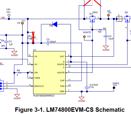
EVM uses 100nF:
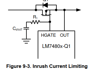
We use slew rate control to limit inrush current as described in datasheet:
To my question: actually, in another schematic, we use another TI part (TPS1211-Q1, Smart High-Side Driver With Protection and Diagnostics).
There is a similar slew rate control circuit:
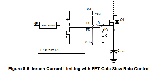
Datasheet of TPS1211-Q1: C1 results in an additional loading on CBST to charge during turn-ON. Use Equation 4 to calculate the required
CBST value.
CBST > Qg(total) + 10 × C1 (4)
Where, Qg(total) is the total gate charge of the FET.
My question: Is the formula of datasheet LM7480-Q1 "Ccap (µF) ≥ 10 x ( CISS(MOSFET_Q1) + CISS(MOSFET_Q2) ) (µF)" sufficient, or should the formula of TPS1211-Q1 also be noticed? In our case, this would result in a larger value of Ccap (min. 174nF with LM7480-Q1's formula, min. 287nF with TPS1211-Q1's formula). Of course, these parts are not really comparable.
Regards, Oliver.
