This thread has been locked.

If you have a related question, please click the "Ask a related question" button in the top right corner. The newly created question will be automatically linked to this question.

BQ25798: How and when ACRB1_STAT is updated

Part Number: BQ25798

Tool/software:

Dear Sirs and Madams,

We are mass-producing equipment that uses the BQ25798, and we are experiencing a problem with the power path circuit.

/* ACBR MOS FETs datasheet URL */

RQ3E180BNTB: Nch 30V 39A Middle Power MOSFET

When USB (5V) is connected to IN1 without applying voltage to IN2, nearly 3% of mass-produced units do not output 5V to VBUS.

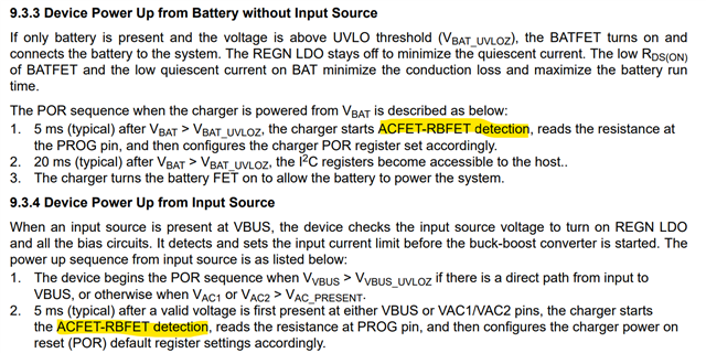
When I checked each register of the BQ25798, I found that ACFET1-RBFET1 Status was set to '0' (Not Present).

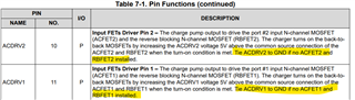
Could you please tell us how ACRB1 determines that it is "placed"?

When does ACRB1 update "placed/NOT placed"?

Regarding the power path circuit, please let us know if there are any problems such as "IN1 gate resistance is large", "FET Qg is high", "VBUS capacitor capacitance is large", or "G-S capacitor capacitance is large".


Regards,

Masashi

  • Hi Masashi,

    The device would look at if ACDRVx is short to ground to determine whether ACFET-RBFET was detected at power on.

    You can refer to datasheet section 9.3.3 and 9.3.4 to when this detection is done.

    Can you share schematic with all the portion related to the BQ25798? 

  • Hello Jing,

    You said:

    "The device would look at if ACDRVx is short to ground to determine whether ACFET-RBFET was detected at power on."

    I have already checked those item.

    Our customer would like to know how to detect ACFET-RBFET in order to optimize the constants of the power path circuit of IN2.

    In other words, our customer is looking for information about the "internal block diagram of the circuit that determines ACRB1_STAT", "method of determining ACRB1_STAT", and "criteria for determining ACRB1_STAT" for BQ25798.

    Regards,

    Masashi

  • Additional infomation,

    Since this problem does not occur on the IN2 side, we found that the problem can be solved by setting the peripheral component constants of the FET used in IN1 to the same constants as IN2.

    I suspect that in order to check the connection of ACRBx, ACDRVx momentarily outputs 'H' to check the potential of VACx and VBAT.

    In the current IN2 configuration, isn't the problem that the gate resistance (R2) is high, and the time constant with the capacitor (C1) prevents the FET from turning on, preventing the potentials of VACx and VBAT from rising?

    Could you please tell us how to determine the constants used in the circuit that drives the power path FET, as the data sheet does not include such information?

    Regards,

    Masashi

  • Hi Masashi,

    I cannot say the specifics of how ACRBx stat is determined. The device does need to output in order to determine whether or not the pin is shorted to GND. Using the same peripherals on IN1 and IN2 should be okay. What is the consideration for having the two be different?

    The typical application in the datasheet has a 294 Ohm resistor into the gate with the zener diode connected in reverse bias to the source.

    Best regards,
    Michael

  • Hello Michael,

    This is just a guess based on our customer's circuit, but I understand that the USB input (IN2) has a soft start configured using a CR time constant.

    The BQ25798 datasheet doesn't have much information on how to design the power path circuit, does it?

    The Qg or Ciss of ACFET and RBFET also affects their operation, right?

    We have selected the peripheral circuits based on previous threads, but what is the best way to select them?

    (+) BQ25798: IINDPM - Power management forum - Power management - TI E2E support forums

    Regards,

    Masashi

  • Hi Masashi,

    No, the input MUX FETs are expecting a fast turn on input source, sensed by VACx.  They are intended to be used as med-fast turn-on switches.

    Yes, Qg/Ciss of the MUX FETs affect their turn on time because the ACDRVx charge pump outputs have output drive current in the 10-100 of nA range.

    We have not tested ACFET and RBFET configurations that are different from those on the BQ25798EVM.  We also have no data on input sources that are slowly soft started (slower than USB-C turn on). The charger wakes up 5ms after VACx senses a voltage > UVLO (~3.6V).   About 3ms after that, ACDRVx charge pump turns on.  About 150ms after that, the charger performs poor source detect, where it pulls up to 30mA current from VBUS and monitors for VBUS to collapse.  About 30ms after that, the charger uses the ADC to measure VBUS voltage and set the VINDPM threshold. 

    The potential issue I see from a slow turn on input source is falsely tripping poor source or VINDPM threshold being set too low. The host can change the VINDPM threshold at any time.

    Regards,

    Jeff

  • Hello Jeff,

    The time constant is set to within 30 ms, but there are some products for which the ACFET1-RBFET1 Status becomes "Not present".

    We know that this issue is influenced by the following relationships: high gate resistance, higher Qg/Ciss than EVM, high G-S capacitance, and Schottky diode for fast turn-off.

    However, we are stumped because there is no information available to design optimal values for these constants about the power path circuit.

    Also, ACDRx drives are not specified in the datasheet.

    Could you please tell us how and when ACBR_STAT determines whether a value is "Presant"?

    Regards,

    Masashi

  • HI Masashi,

    At power up, the ACDRVx pins output ~40 uA from an internal ~5V rail.  If the voltage at ACDRVx does not rise above 1V in 2ms, the charger decides that the ACDRVx pins are not present.

    Regards,

    Jeff

  • Hello Jeff,

    Thank you for providing very useful information.

    The BQ25798 has two power-up sequences: battery only and input source. If I connect a valid battery and complete the power-up sequence "9.3.3 Device Power Up from Battery without Input Source", is it correct to understand that "9.3.4 Device Power Up from Input Source" will not be executed?

    Regards,

    Masashi