This thread has been locked.

If you have a related question, please click the "Ask a related question" button in the top right corner. The newly created question will be automatically linked to this question.

LM5156: Feedback loop compensation with single inductors

Part Number: LM5156
Other Parts Discussed in Thread: LM5155,

Tool/software:

Hi TI,

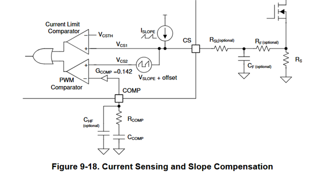
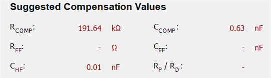
How do I use "Power Stage Designer" and Excel "LM5155 LM5156 Quickstart Calculator for SEPIC" to select feedback loop compensation components for LM5156 in SEPIC topology?
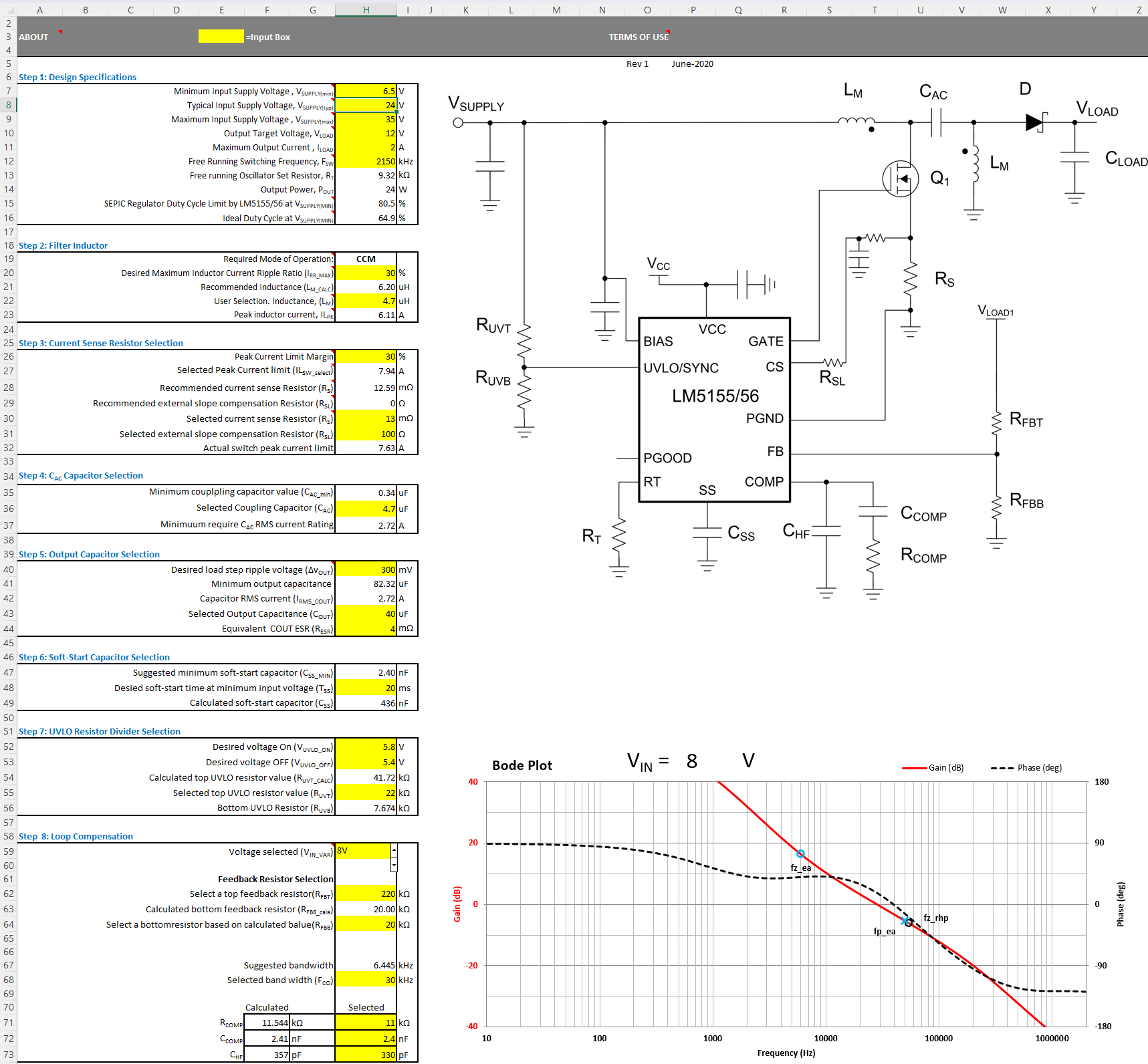
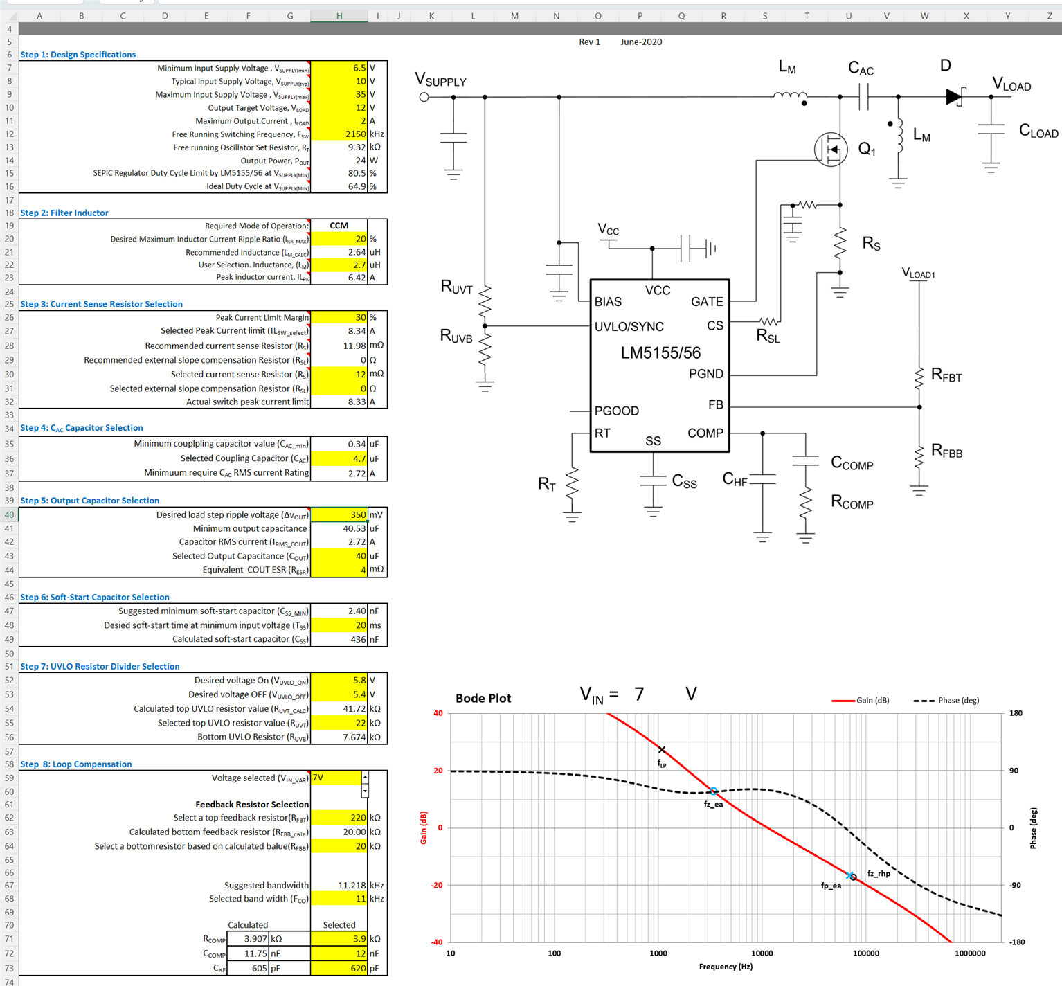
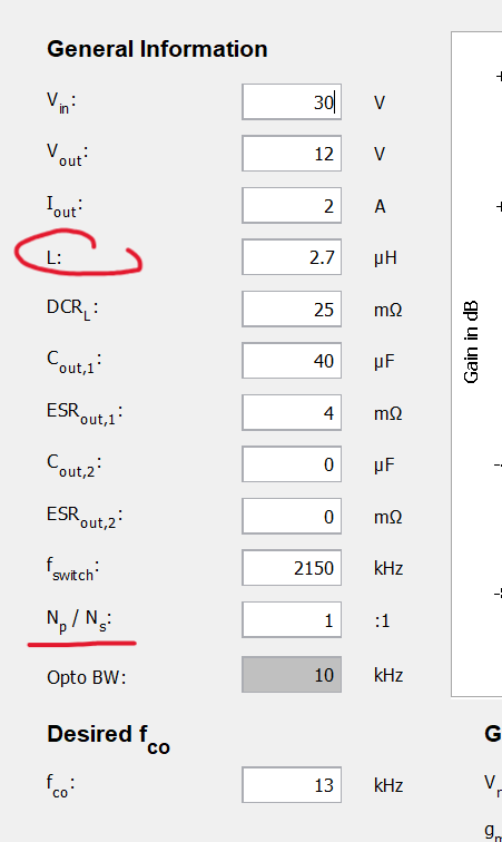
My goal is to design 12V/2A SEPIC SMPS with Vin 6.5-35V optimized for 10-30V range. Probably the most optimal inductors selection is L1=2.7 or 3.3µH, L2=4.7µH DCRL=38m. Derated Cout=40µF, ESR=4mΩ at fSW=2.15MHz.
In my design I cannot use coupled inductors. Making custom ones is not feasible and there is also max height requirement which coupled inductors typically do not meet.
SMPS will be used to power circuits driven GPIOs, rather than audio frequencies, so probably I should select higher fcross.

1. For the feedback loop calculations only L2 value needs to be considered, and I am not certain what value should be entered in TI Excel spreadsheet cell H22 (LM). Should I enter the selected L2 value or only half of this value? TI Excel spreadsheet probably assumes coupled inductors are used.

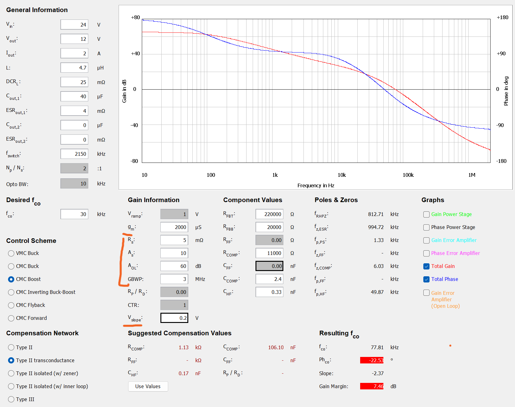
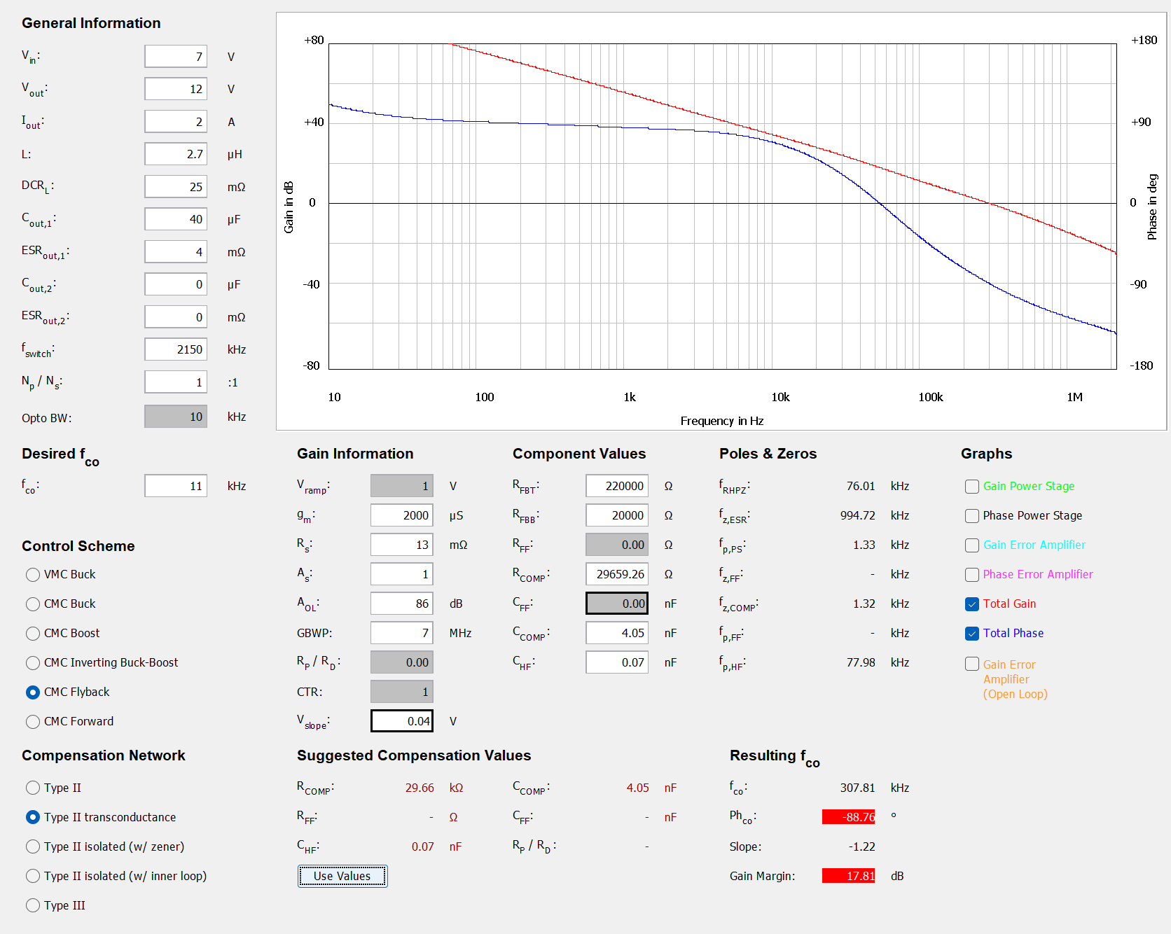
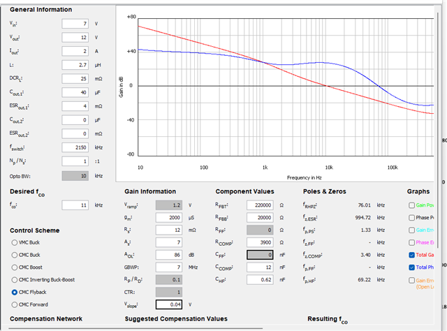
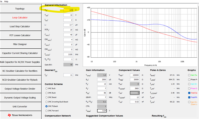
2. How to properly configure and use "Power Stage Designer"? SEPIC is not one of the available "Control Schemes".
Do I correctly assume that "Type II Transconductance" compensation network has to be selected?
What highlighted values should I enter for LM5156? (see image below)

3. DeepSeek provides the following advice:
a. place fz_ea below fcross (typically 1/5th to 1/10th of it)
b. place fp_ea above fcross (but below fSW/2)
c. set fcross ≤ fz_rhp/3
d. ofc, phase margin at fcross has to be 
≤ 45° (phase -135° max)
Could you confirm the above makes sense?

In my case DeepSeek suggests target fcross=50kHz, but it may not be achievable with Type II compensator. However, fcross=40kHz seems achievable.

Please advise.

Kind regards,
Thomas

  • Hi Thomas, 

    Thanks for using E2E.

    In this case, the excel spreadsheet is not the best way to do the compensation calculation, because it assumes coupled inductors. But with the power stage designer you can easily do it. 

    To compensate a SEPIC, please use CMC Flyback scheme. Type 2 transconductance is right. 

    The derivation of the SEPIC powerstage is very complex, You can find papers online. Thats why designers use the flyback scheme (which is very similar). The loop will be stable when compensating for flyback, and if there is fine tuning necessary this will be done in the lab. 

    Regarding the values you are missing:

    -Rs is the current sense resistor you use

    - As is the current sense gain (it is 1 for LM5155 and LM5156)

    - Aol for a transconductance amplifier is calculated by gm * Rout (Rout is 10Mohm from the datasheet 9.3.9)

    - The GBWP is calculated with the gain multiplied with the BW which is 7MHz (9.3.9)

    - to calculate Vslope please use formula 7 in chapter 9.3.7

    I hope this helps to use the powerstage designer for your compensation.

    If you have further questions please feel free to ask.

    Best regards

    Moritz

  • Hi Moritz,

    Thank you for the clarification!

    To simplify the loop compensation analysis/design, at least for now I'll follow the Excel calculator's recommendation and use a 2.7μH coupled inductor.

    First of all, does it mean I should use two coupled inductors, each winding 2.7µH OR 2.7µH is the total effective inductance?

    I attempted to input Excel-calculated values into Power Stage Designer, but it computed completely different Ccomp/Rcomp/CHF values and drew much different Bode plot. What am I missing?

    To proceed with reasonable confidence, before attempting lab tests I need to resolve this issue thoroughly - and I believe this topic may be of interest to others as well.
    My primary concerns are stability at low Vin (6.5V) and low EMI from Vin=10V.
    Both Excel and Power Stage Designer files attached.

    Kind regards,

    Thomas

    LOOP_CALCULATOR
    7
    12
    2
    2.7
    25
    40
    4
    0
    0
    2150
    1
    10
    11
    5
    2
    1
    2000
    13
    1
    86
    7
    0.00
    1
    0.04
    1
    220000
    20000
    0.00
    29659.26
    0.00
    1
    4.05
    0.07
    TI LM5155 LM5156 Quickstart Calculator for SEPIC.xlsx

  • Hi Thomas,

    does it mean I should use two coupled inductors, each winding 2.7µH OR 2.7µH is the total effective inductance?

    It means that you use one coupled inductor package, where two single inductors are coupled inside with a inductance of 2.7uH each.

    Regarding the different bode plots, i found the issue. 

    The CS amplifier gain of LM5156 is ideed 1, however, it uses a COMP gain instead, to reduce COMP voltage with a gain of 0.142. See datasheet:

    So setting As to 7 is the right way. 

    This will also make the plots very similar.

    Best regards

    Moritz

  • Hi Moritz,

    Thank you for the clarification - that helps explain the difference.

    I noticed that Power Stage Designer suggests significantly different values for Ccomp, Rcomp, and CHF compared to the Excel calculator.
    I'm not implying that either set of values is incorrect, but the discrepancy is a bit surprising - unless, of course, there’s more than one valid way to stabilize this SMPS at low Vin. Am I correct in assuming that the difference stems from the fact that the Excel calculator considers the entire specified input voltage range, while Power Stage Designer calculates values based on a single, specified Vin?If that's correct, it seems the Excel calculator may provide a more comprehensive and much more useful approach.

    One last question: In Power Stage Designer, when simulating a SEPIC with two separate inductors (L1 ≠ L2), how should the 'L' and 'Np/Ns' values be configured?
    Specifically, is the 'L' parameter in the tool meant to represent the average of L1 and L2, just L1, or another value?

    Kind regards,

    Thomas

  • Hi Thomas, 

    In power stage designer as well as in the excel calculator you can set the input voltage for which you want to compensate:

    I dont exactly know why the recommended values are different, i would need to check how the calculations are done in side the tools, but there is not only one way to set a pole or a zero to a certain frequency.

    Specifically, is the 'L' parameter in the tool meant to represent the average of L1 and L2, just L1, or another value?

    You should use the higher inductance value in this case. Because the higher value will put the RHPZ to lower frequencies.

    Best regards

    Moritz

  • Hi Thomas,

    Many thanks for your support.
    Probably in most cases (always?) the higher L value would be L2. But why does it require Np/Ns?
    It is a bit puzzling but perhaps some mystery should remain.

    In summary, the Excel calculator does quite good job, and its suggested feedback loop components can be successfully verified - at least in my case - using Power Stage Designer.

    Kind regards,

    Thomas

  • Hi Thomas, 

    For SEPIC there is no Np/Ns required. Powerstage designer only wants you to enter it because you selected the flyback compensation scheme. So you can put it to 1:1 and ignore it. 

    Best regards

    Moritz